Heat-dissipating fan fixing device

a technology for fixing devices and fans, applied in electrical equipment, electrical apparatus, electrical apparatus contruction details, etc., to achieve the effect of saving the case area

Inactive Publication Date: 2009-02-24
INVENTEC CORP
View PDF25 Cites 17 Cited by
  • Summary
  • Abstract
  • Description
  • Claims
  • Application Information

AI Technical Summary

Benefits of technology

[0008]According to the above prior art, a user needs to use assembling tools to lock and fix the heat-dissipating fans on the case, which is time-consuming, and quite a lot of case area is occupied by a plurality of heat-dissipating fans. Accordingly, an objective of the present invention is to provide a heat-dissipating fan fixing device, which enables the user to assemble the heat-dissipating fan on the case without using any tools and saving the case area occupied by heat-dissipating fans.
[0011]According to the heat-dissipating fan fixing device disclosed by the present invention, the hooks of the heat-dissipating fan fixing device are used to assemble the heat-sink fan on the case, without using any tools and locking elements, so as to simplify the stacking and assembling process and reduce the time for assembling. Meanwhile, the positioning pieces and the buckle base at another end are used to join the frame with another frame on the original case position, so as to be continuously stacked and assembled into a heat-dissipation structure with a plurality of heat-dissipating fans, thereby saving the case area occupied by heat-dissipating fans. In addition, the number of the required heat-dissipating fans may be increased or reduced according to the requirements of the heat-dissipation efficiency. For example, when it is intended to increase or reduce the heat-dissipation efficiency, the number of the stacked and assembled heat-dissipating fans may be increased or reduced accordingly, which has a large using variation flexibility.

Problems solved by technology

According to the above prior art, a user needs to use assembling tools to lock and fix the heat-dissipating fans on the case, which is time-consuming, and quite a lot of case area is occupied by a plurality of heat-dissipating fans.

Method used


Image

  • Heat-dissipating fan fixing device
  • Heat-dissipating fan fixing device
  • Heat-dissipating fan fixing device

Examples


Embodiment Construction

[0020]In order to further understand the objective, construction, feature, and function of the present invention, it is described below in great detail through the embodiments.

[0021]The implementation method of the present invention will be illustrated below through the following specific embodiments. It is easy for those skilled in the art to understand other advantages and efficacy of the present invention through the content of the specification. The present invention also can be implemented and practiced through other different specific embodiments, and the details of the specification may be changed and modified depending upon different viewpoints and applications, without departing from the spirit and scope of the invention.

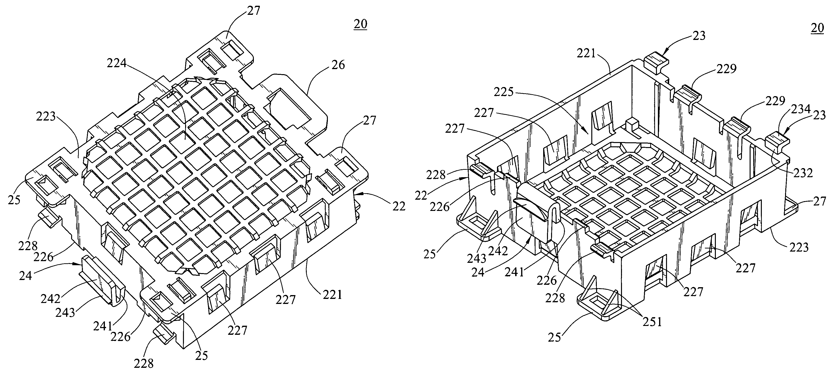
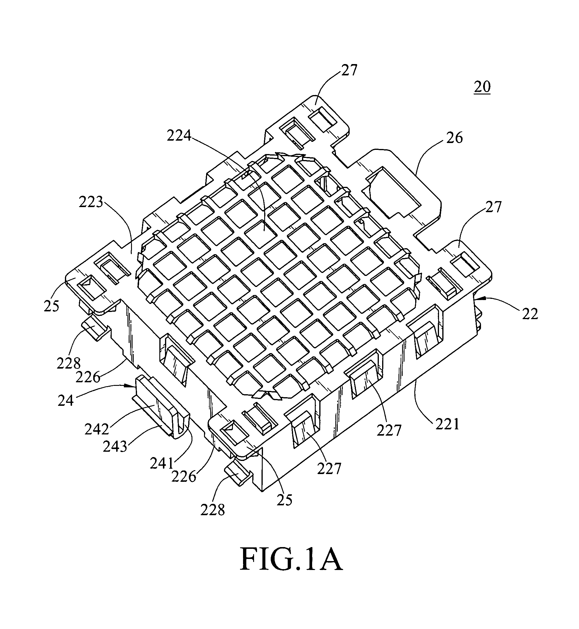
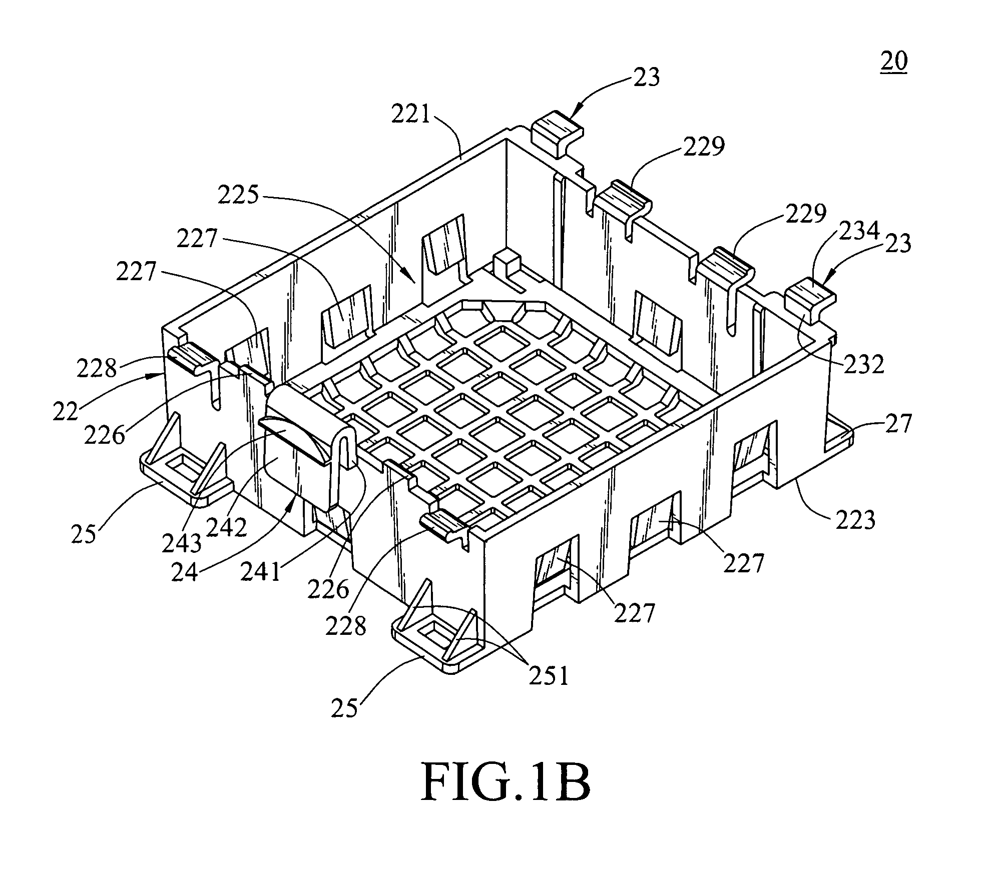
[0022]Referring to FIGS. 1A, 1B, 2, and 3, a heat-dissipating fan fixing device 20 is provided for accommodating and fixing a heat-dissipating fan 40 therein, and it is mounted on a case 50. The heat-dissipating fan fixing device 20 includes a frame 22, a p...


PUM


Abstract

A heat-dissipating fan fixing device used for accommodating and fixing a fan and mounted on a case is provided, which includes a frame, a plurality of hooks and an elastic buckle piece. The frame has a first end and a second end being opposite to each other. Between the first end and the second end, an accommodating space through the frame is formed for accommodating and fixing the fan. The hooks extend from one side edge of the first end, and the elastic buckle pieces are formed by bending along another side wall of the first end. Thus, when the frame is joined with the case, firstly, each hook catches the case, and then, the elastic buckle piece is embedded into the case, thereby mounting the fixing device with the fan on the case.

Description

BACKGROUND OF THE INVENTION[0001]1. Field of Invention[0002]The present invention relates to a heat-dissipating fan fixing device, and more particularly, to a fixing device for stacking a plurality of heat-sink fans thereon according to the heat radiation requirements.[0003]2. Related Art[0004]A main board, a CPU chip, and various disk drivers are installed within a computer case, the above units and elements generate a great deal of heat. In order to prevent the heat from negatively affecting the operation of the computer, it is necessary to take measures to dissipate the heat, so generally the design of a heat-dissipating fan is further required.[0005]In the conventional method for assembling a heat-dissipating fan to a computer case, a plurality of screws or other locking elements are used to fix the heat-dissipating fan on the computer case. It may meet the demands for the computer host in which only one to two heat-dissipating fans are required. However, as for the relatively l...

Claims


Application Information

Patent Timeline
Patent Type & Authority Patents(United States)
IPC IPC(8): H05K7/20
CPCH05K7/20172
Inventor YANG, CHUN-YING
Owner INVENTEC CORP
Why Eureka
Try Eureka