Metal-insulator-metal transformer and method for manufacturing the same

a technology of metal transformers and metal-insulators, applied in the field of inductance, can solve the problems of large size of coplanar transformers, serious impact on device reliability, and high cost, and achieve the effects of increasing the coupling coefficient of transformers, reducing the space between coils, and saving the chip area

Active Publication Date: 2008-04-29
UNITED MICROELECTRONICS CORP
View PDF7 Cites 34 Cited by
  • Summary
  • Abstract
  • Description
  • Claims
  • Application Information

AI Technical Summary

Benefits of technology

[0008]Accordingly, at least one objective of the present invention is to provide a method for manufacturing a metal-insulator-metal transformer capable of effectively saving the area of the chip and decreasing the space between the coils so as to increase the coupling coefficient of the transformer.
[0009]At least another objective of the present invention is to provide a metal-insulator-metal transformer capable of decreasing the space between the coils so as to increase the coupling coefficient of the transformer and the performance and the reliability of the device.
[0026]In the present invention, the metal-insulator-metal transformer according to the present invention can be manufactured by using the conventional metal-insulator-metal capacitor process. Therefore, the area occupied by the transformer on the chip is relatively small so that the cost is decreased. Moreover, the space between the first metal coil and the second metal coil is decreased. Hence, the coupling coefficient and the performance of the transformer of the present invention are enhanced. Additionally, the metal-insulator-metal transformer can be formed together with the metal-insulator-metal capacitor so that the cost is decreased as well.

Problems solved by technology

Therefore, the size of the coplanar type transformer is too large so that size of the radio circuit with the coplanar type transformer is lager as well.
Therefore, the cost is high.
Hence, the performance and the reliability of the device are seriously affected.
With the decreasing of device size, the conventional transformer and the conventional method for manufacturing the transformer cannot full fill the design requirements.

Method used


Image

  • Metal-insulator-metal transformer and method for manufacturing the same
  • Metal-insulator-metal transformer and method for manufacturing the same
  • Metal-insulator-metal transformer and method for manufacturing the same

Examples


Embodiment Construction

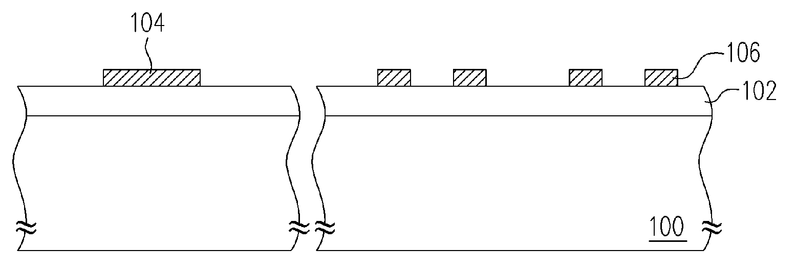
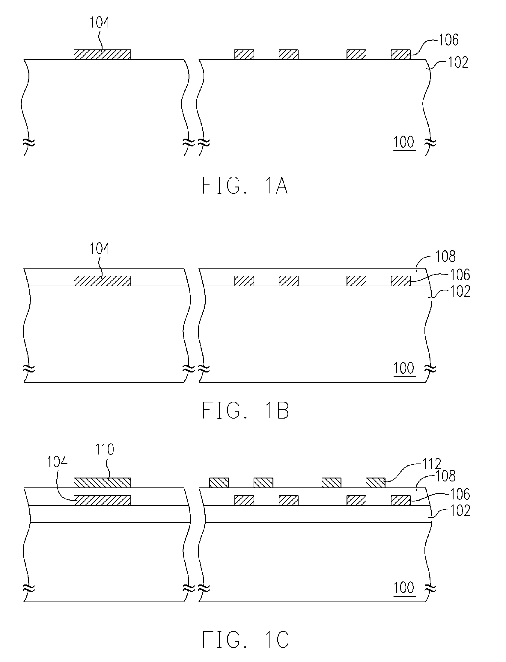
[0038]FIGS. 1A through 1C are cross-sectional views illustrating a method for manufacturing a metal-insulator-metal transformer according to a preferred embodiment of the invention.

[0039]As shown in FIG. 1A, a substrate 100 is provided. The substrate 100 possesses at least one dielectric layer 102 formed thereon. The dielectric layer 102 can be, for example but not limited to, made of silicon oxide, silicon nitride, the dielectric material with low dielectric constant or the other well known dielectric material. The method for forming the dielectric layer 102 comprises steps of performing a chemical vapor deposition process to deposit a dielectric layer (not shown) over the substrate 100 and then performing a planarizing process by using the chemical mechanical polishing. The dielectric layer 102 can be, for example, a complex layer having a multi-layered structure. Furthermore, on the substrate 100 and within the dielectric layer 102, there are several devices and metal interconnec...


PUM

PropertyMeasurementUnit
inductanceaaaaaaaaaa
magnetic fluxaaaaaaaaaa
structuresaaaaaaaaaa

Abstract

The invention is directed to a method for manufacturing a metal-insulator-metal transformer together with a capacitor. The method comprises steps of providing a substrate having at least a dielectric layer formed thereon and then forming a first metal layer of the metal-insulator-metal capacitor together with a first metal coil of the transformer over the substrate. An insulating layer is formed to cover the substrate, the first metal layer and the first metal coil. A second metal layer of the metal-insulator-metal capacitor is formed together with a second metal coil of the transformer on the insulating layer.

Description

BACKGROUND OF THE INVENTION[0001]1. Field of Invention[0002]The present invention relates to an inductance and a manufacturing method thereof. More particularly, the present invention relates to a metal-insulating-metal transformer and the manufacturing method thereof.[0003]2. Description of Related Art[0004]Currently, since the transformer possesses the advantages including high efficiency, no magnetic leakage and low noise, the transformer becomes one of the essential elements in the radio integrated circuit. Moreover, the transformer is widely used in many applications such as microwave and radio frequency circuit.[0005]The transformer is composed of a core and two coils, primary coil and secondary coil. Generally, the core is used as a medium and two coils are wound around the core. While the alternating current is applied onto the primary coil, a magnetic flux which is perpendicular to the coils is generated within the core. According to the magnetic flux within the core, a vol...

Claims


Application Information

Patent Timeline
Patent Type & Authority Patents(United States)
IPC IPC(8): H01F5/00H01F7/06
CPCH01F27/2804H01F27/40H01F41/041H01L23/5223H01L23/5227H01L28/10H01L28/40H01F17/0006Y10T29/4902H01F2027/2809H01L2924/0002H01L2924/00
Inventor YEN, ALBERT KUO HUEIWU, CHANG-CHINGHUANG, CHIH-YANG
Owner UNITED MICROELECTRONICS CORP
Why Eureka
Try Eureka