Hologram apparatus and hologram recording method

a technology of hologram apparatus and recording method, which is applied in the field of hologram apparatus, can solve the problems of difficult to apply the tracking servo at the time of reproduction, difficult to apply the tracking servo in the cross-track direction, etc., and achieves the effect of increasing tolerance, easy and stably performing the tracking servo, and increasing toleran

Inactive Publication Date: 2009-02-24
SONY CORP
View PDF4 Cites 3 Cited by
  • Summary
  • Abstract
  • Description
  • Claims
  • Application Information

AI Technical Summary

Benefits of technology

[0010]Thus, there is a need for a hologram apparatus and a hologram recording method by which it is possible to easily and stably achieving the tracking servo at the time of reproduction, by recording under an increased tolerance in the cross-track direction while securing the shift selectivity necessary in the track direction of the recording area of a hologram recording material.
[0012]Thus, in an embodiment of the present invention, for example, the hologram recording material is irradiated with the reference beam having been passed through a diffuser plate shaped to be elongate in the track direction of the recording area of the hologram recording material, whereby the reference beam having a speckle pattern having a larger granular shape in the cross-track direction than the track direction of the recording area is produced, and recording is conducted by irradiating the recording area of the hologram recording material with the reference beam having the speckle pattern. Therefore, it is possible to perform recording under an increased tolerance in the cross-track direction while securing the shift selectivity necessary in the track direction, and, hence, to easily and stably perform the tracking servo at the time of reproduction.
[0013]According to the present invention, by using the reference beam different in form of the speckle pattern in the track direction and the cross-track direction of the recording area of the hologram recording material, it is possible to perform recording under an increased tolerance in the cross-track direction while securing the shift selectivity necessary in the track direction, and, hence, to easily and stably perform the tracking servo at the time of reproduction.
[0014]In addition, owing to the above effect, the recording density in the track direction in the recording area of the hologram recording material can be enhanced without being bundled by the limit of tracking servo, and, therefore, the recording density can be raised to the upper limit determined by the dynamic range of the recording material.

Problems solved by technology

The high selectivity is necessary in the shifting direction, but it makes it difficult to apply the tracking servo in the cross-track direction.
Specifically, it is difficult to apply the tracking servo at the time of reproduction, unless the shift selectivity in the cross-track direction is lowered, i.e., unless the tolerance in the cross-track direction is increased.

Method used


Image

  • Hologram apparatus and hologram recording method
  • Hologram apparatus and hologram recording method
  • Hologram apparatus and hologram recording method

Examples


example 1

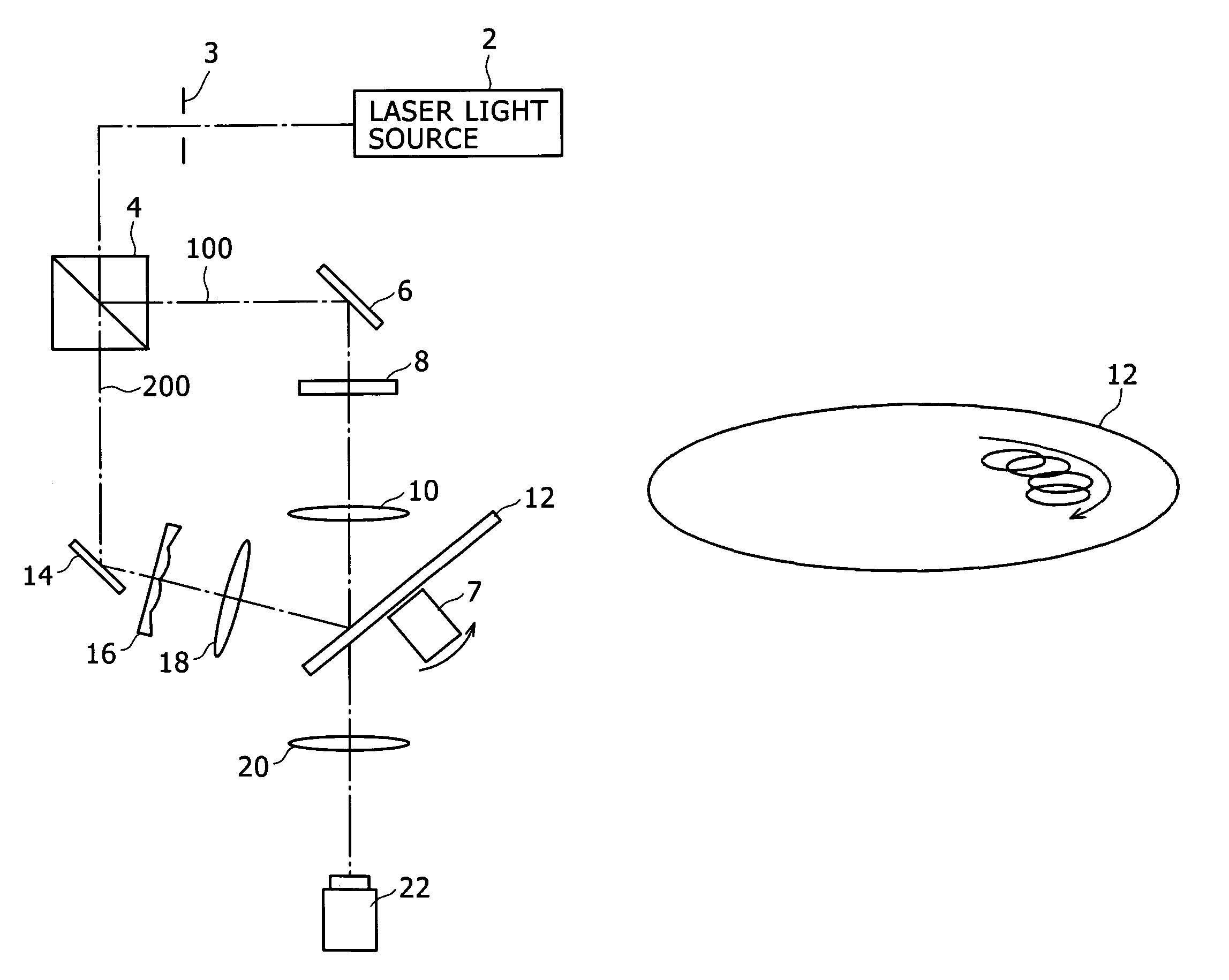
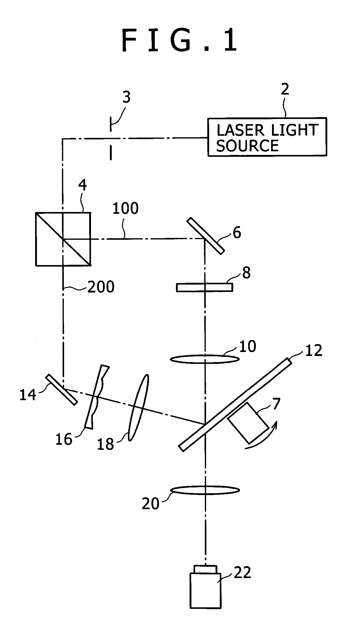
[0028]FIG. 1 is a schematic diagram showing the configuration of a hologram recording / reproduction apparatus according to a first embodiment of the present invention. The hologram recording / reproduction apparatus includes a laser light source 2, a shutter 3, a beam splitter 4, a mirror 6, a space light modulator 8, a lens 10, a disk form hologram recording material (made of a photopolymer or the like) 12, a mirror 14, a diffuser plate 16 for dispersing a reference beam 200 to render the wave front speckle-like in shape, a lens 18, a lens 20, a detector 22, and a spindle motor 7.

[0029]Now, the operation of this embodiment will be described. In FIG. 1, in the case of recording data on the hologram recording material 12, with the shutter 3 in a closed state, the data page to be recorded is displayed on the space light modulator (transmitting liquid crystal display apparatus) 8, the spindle motor 7 is rotated to determine the recording site (recording area) of the hologram recording mat...

example 2

[0040]FIG. 6 is a plan view showing the configuration of a major part of a hologram recording / reproduction apparatus according to a second embodiment of the present invention. It should be noted here that the same portions as those in the first embodiment above will be denoted by the same symbols as used above, in the following description. A reference beam optical system in the hologram recording / reproduction apparatus in this embodiment has an aperture 25, and a reference beam having passed through a diffuser plate is led through the aperture 25 to irradiate a hologram recording material 12 therewith.

[0041]FIG. 7A is a side view of FIG. 6 as viewed in the direction of arrow A, and FIG. 7B is a side view of FIG. 6 as viewed in the direction of arrow B. The reference beam optical system of the hologram recording / reproduction apparatus includes the diffuser plate 16, a lens 24, the aperture 25, and a lens 26. The lens 24 and the lens 26 constitute a 4f optical system, which is a kind...

example 3

[0046]FIG. 8 is a plan view showing the configuration of a major part of a hologram recording / reproduction apparatus according to a third embodiment of the present invention. It should be noted here that the same portions as those in the second embodiment above will be denoted by the same symbols used above, in the following description. A reference beam optical system in the hologram recording / reproduction apparatus in this embodiment has a structure in which a reference beam 200 having passed through a diffuser plate 16 mounted to the opening of an aperture 25 is led to irradiate a hologram recording material 12 therewith.

[0047]FIG. 9A is a side view of FIG. 8 as viewed in the direction of arrow A, and FIG. 9B is a side view of FIG. 8 as viewed in the direction of arrow B. The reference beam optical system of the hologram recoding / reproduction apparatus includes the aperture 25 mounted to the opening of the diffuser plate 16, and a lens 27, which functions as Fourier transform len...


PUM

PropertyMeasurementUnit
areaaaaaaaaaaa
diffusion angleaaaaaaaaaa
shapeaaaaaaaaaa

Abstract

The present invention provides a hologram apparatus for recording an interference fringe of a signal beam and a reference beam having a speckle pattern in a recording area of a hologram recording material. The hologram apparatus includes a speckle pattern generating unit for generating the speckle pattern so that the speckle pattern is different in form in the track direction and the cross-track direction of the recording area. With this configuration, it is possible to perform recording under an increased tolerance in the cross-track direction while securing the shift selectivity necessary in the track direction, and, hence, to easily and stably perform the tracking servo at the time of reproduction.

Description

BACKGROUND OF THE INVENTION[0001]The present invention relates to a hologram apparatus for performing volume recording of a hologram on a hologram recording material, and particularly to a hologram recording method for easily performing tracking servo at the time of reproduction.[0002]In recent years, there have been proposed holographic storage systems for recording / reproduction of a large capacity of data by utilizing the hologram technology. The holographic storage systems include a recording system in which a hologram recording material (hereinafter sometimes referred to simply as recording material) is irradiated, at predetermined angles, with both a signal beam including recording data generated by space light modulation means such as a liquid crystal device and a reference beam set according to the signal beam so that an interference fringe generated by the signal beam and the reference beam is recorded on the recording material, and a reproduction system in which the hologra...

Claims


Application Information

Patent Timeline
Patent Type & Authority Patents(United States)
IPC IPC(8): G11B7/00G11B7/0065G11C13/04
CPCG11B7/0065G11C13/042
Inventor KIHARA, NOBUHIROYAMATSU, HISAYUKIEZURA, MEGUMI
Owner SONY CORP
Why Eureka
Try Eureka