Method and apparatus for extending the lower frequency operation of a sampler based VNA

a sampler and lower frequency technology, applied in the field of methods and apparatus for extending the lower frequency operation of a sampler based vna, can solve the problems of the pulse rate of the generated pulse, and achieve the effect of wide frequency operation range and limited nois

Inactive Publication Date: 2009-03-24
ANRITSU CO
View PDF8 Cites 18 Cited by
  • Summary
  • Abstract
  • Description
  • Claims
  • Application Information

AI Technical Summary

Benefits of technology

[0016]In accordance with the present invention, circuitry is provided that allows a sampler to operate many octaves below its previously designed lowest frequency. With a wider frequency operation range using the SRD, only one downconversion is required, eliminating the need for mixers and a second LO signal generator, as well as switches to bypass the harmonic samplers in a “direct mode.”
[0017]The circuitry to drive the SRD according to the present invention uses a digital pulse generator to provide LO drive pulses with limited noise. The fact that the LO frequency source oscillator has a limit of an octave range can still be met, but pulse rate is controlled by pulse forming circuitry including a variable digital frequency divider. Pulse width is further controlled by registers connected to the frequency divider so that long pulse widths do not unnecessarily heat the SRDs. The pulse rate can be adjusted to any sub multiple of the LO generating oscillator signal frequency down to approximately 3 times the signal FIF using the variable frequency divider. The Nyquist rate would be 2 times FIF, but aliasing in the form of spurious IF responses would corrupt the harmonic sampler output below this 3 times rate. The increased range of pulse rates enables a single LO signal to downconvert a much wider range of RF signals to IF with a single downconversion than previous circuits that use an analog drive circuit for the SRD.

Problems solved by technology

The noise will cause deviations in the pulse rate of pulses generated by the SRD.

Method used


Image

  • Method and apparatus for extending the lower frequency operation of a sampler based VNA
  • Method and apparatus for extending the lower frequency operation of a sampler based VNA
  • Method and apparatus for extending the lower frequency operation of a sampler based VNA

Examples


Embodiment Construction

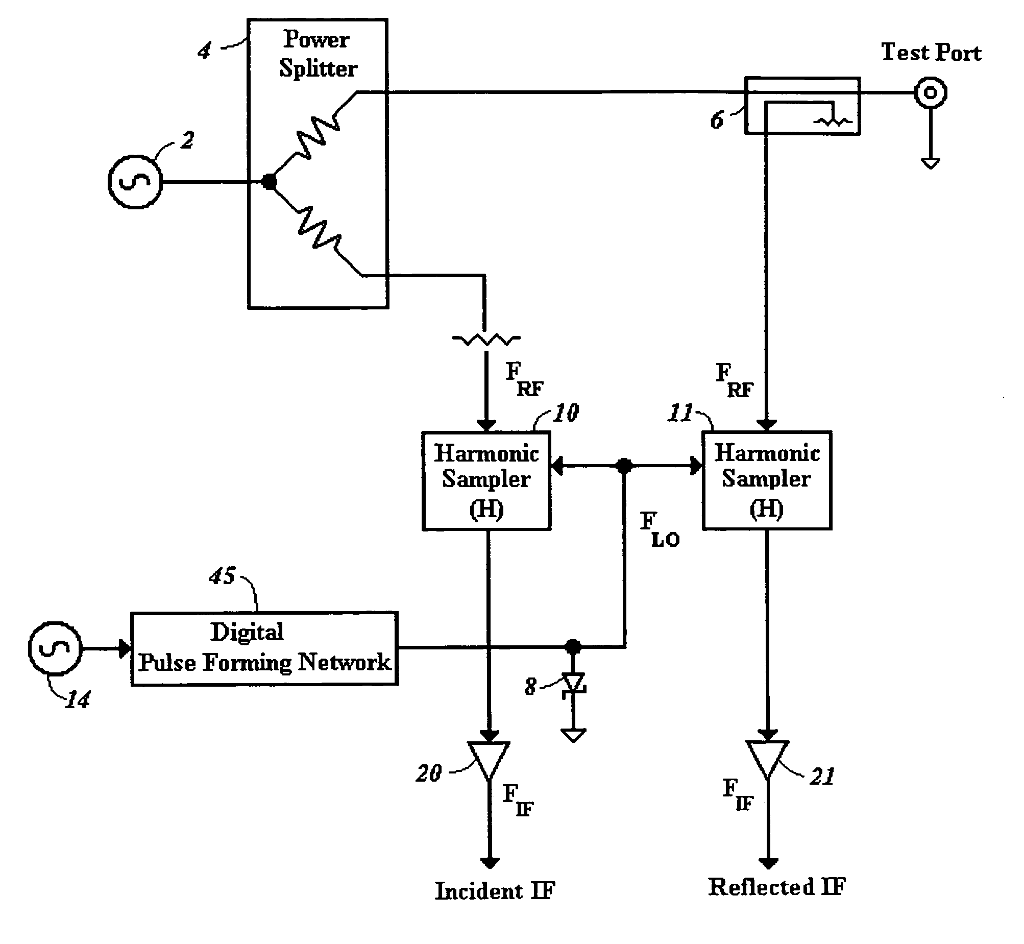
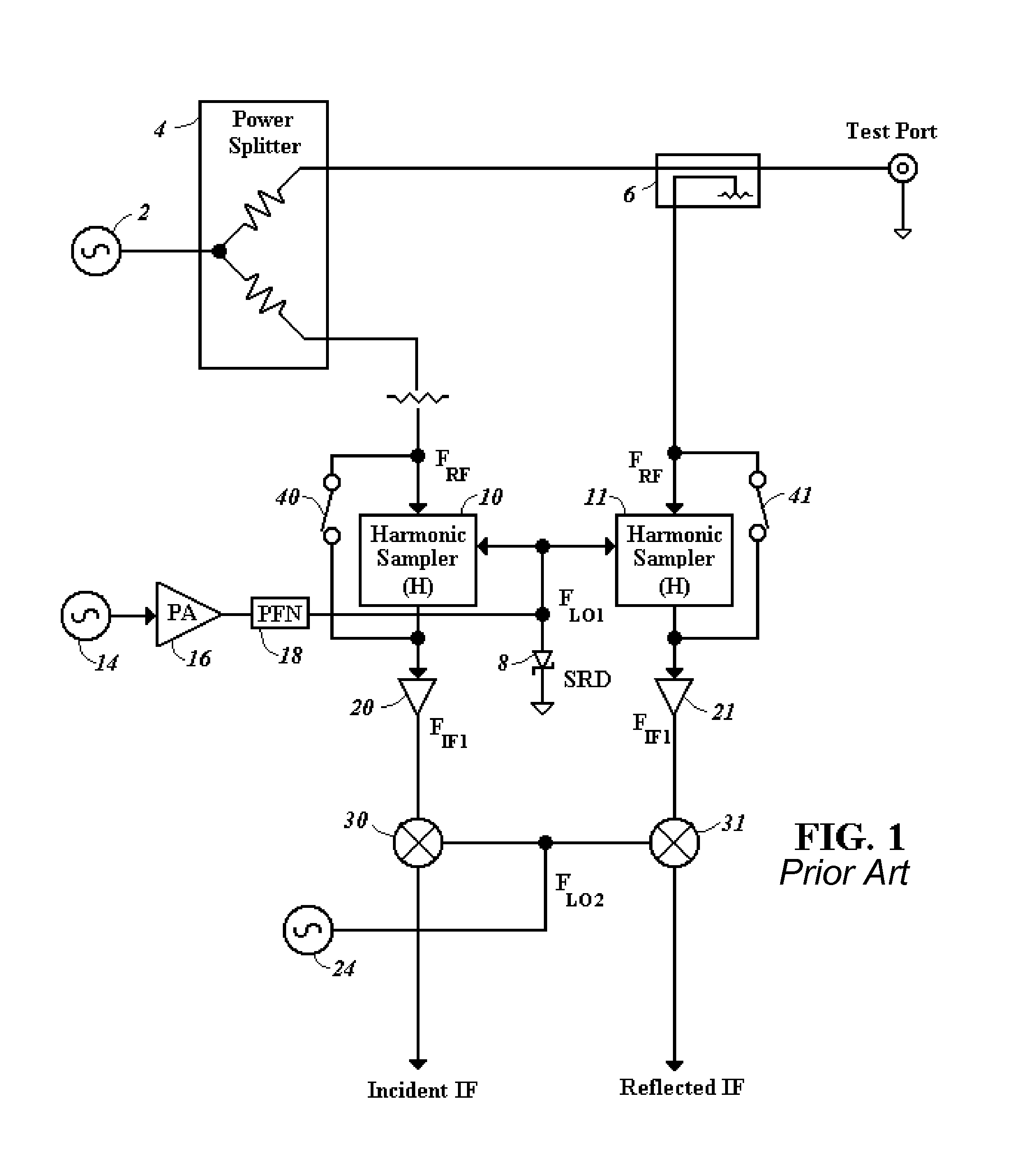
[0027]FIG. 4 shows modifications to the circuitry of FIG. 1 to include a digital pulse forming network 45 for providing signals to the SRD 8 in accordance with the present invention. The digital pulse forming network 45 having circuitry described to follow allows a low noise LO pulse to be provided to the SRD 8 over a wider frequency range than by using the amplifier 16 and PRN 18 of FIG. 1, that are removed. With the wider range of LO signals, the additional circuitry for a second down conversion is further eliminated from FIG. 4, including the mixers 30 and 32 and LO source 24. The bypass switches 40 and 41 to provide a direct mode are further eliminated in FIG. 4 since only one downconversion is used for all RF frequencies.

[0028]FIG. 5 shows a digital pulse generator circuitry 46 for use in the digital pulse forming network 45 of FIG. 4. The digital pulse generator 46 includes a programmable divide by N frequency divider 50 along with registers 52 and 54 all connected to receive ...


PUM


Abstract

Circuitry is provided to drive a step recovery diode (SRD) (8) in a sampler based vector network analyzer (VNA) that allows harmonic samplers (10, 11) to operate over many octaves. The circuit includes a digital pulse generator (FIG. 5) for providing a LO signal. The LO signal is provided over an octave frequency range as in previous SRD driver circuits, but pulse forming circuitry is provided to decrease the pulse rate to a sub multiple of the LO generating oscillator signal. The pulse forming circuitry includes a programmable frequency divider (50) to vary the pulse rate. The pulse forming network further includes registers (50, 52) connected to the programmable frequency divider (50) to limit the pulse width resulting in reduced heating of the SRDs. With an effectively wider frequency operation range using the SRD (8), only one downconversion is required in the VNA, eliminating the need for additional mixers (30, 31) and a second LO signal generator (24) to provide a second downconversion.

Description

BACKGROUND[0001]1. Technical Field[0002]The present invention relates to components for generating a signal to drive a step recovery diode (SRD) of a sampler based vector network analyzer (VNA).[0003]2. Related Art[0004]To generate and downconvert high frequency RF signals in a VNA, harmonic samplers are used with higher order harmonics selected for downconversion by an appropriate LO signal when high frequency signals are desired. To generate high frequency LO signals to apply to the harmonic samplers for downconverting the higher order harmonics, a step recovery diode (SRD) is used to generate LO pulses with sufficient power and frequency for the downconversion.[0005]A conventional VNA uses a multiple step downconversion process for high frequencies. A first downconversion is performed with harmonic samplers and a high frequency LO signal. A second downconversion is then performed to further reduce frequency to a baseband using a mixer and a low frequency LO signal.[0006]In such a...

Claims


Application Information

Patent Timeline
Patent Type & Authority Patents(United States)
IPC IPC(8): H03K5/01
CPCG01R27/28H03K5/1534H03K7/08
Inventor BRADLEY, DONALD ANTHONY
Owner ANRITSU CO
Why Eureka
Try Eureka