
High-efficient ion source with improved magnetic field

a high-efficiency, magnetic field technology, applied in the field of ion and plasma source technology, can solve the problems of reducing the lifetime of the ion source, and providing a higher emission current and a much longer lifetime, so as to reduce the damage, the initial ionization is higher and uniform, and the operation parameters are wide.

Inactive Publication Date: 2005-10-27
ZHURIN VIACHESLAV V
View PDF7 Cites 29 Cited by
  • Summary
  • Abstract
  • Description
  • Claims
  • Application Information

AI Technical Summary

Benefits of technology

[0037] In light of foregoing, it is an object of the invention to introduce an ion source of a Hall-current type with improved positive magnetic field gradient. Such magnetic field configuration in a cylindrical and cone shape discharge channel makes possible to suppress oscillations and instabilities.
[0039] Still another object of the present invention is to expand operating conditions of the invented ion source for discharge voltages from about 20 V to over 1000 V, and for discharge currents from about 1 A to over 20 A, so a total power applied to the invented ion source can be about 1.5-2 kW without a water cooled anode, and substantially and over 10 kW with a water cooled anode.
[0040] Yet a further object of the present invention is to make an ion source with wider range of operation parameters at different magnetic field distributions. This flexibility is provided by following means: a) a placement of magnets in area around a discharge region; b) a placement of a magnetic shunts around an anode area, so that magnetic field lines will go around this magnetic shunt and will develop a positive magnetic gradient in a discharge region, and an anode will be in area with minimum of magnetic field; c) by a gas feed area under anode, this gas volume is a subject of electrons penetration into area under anode and a photo-ionization radiation from a region of ionization and acceleration located downstream from anode area; this gas volume provides a working gas into a discharge area with more higher and uniform initial ionization; d) working gas supplied into a gas volume goes through a series of small holes placed on a periphery of an external magnetic screen with holes having inclination so, that working gas is introduced through a tangential entrance with development of a vortex flow that provides uniform distribution of working gas into gas volume under anode and into anode area.
[0041] A further object of the present invention is to provide potential distribution conditions that help to have acceleration of ions mainly in a discharge chamber exit close to a maximum of magnetic field distribution. Such a potential distribution helps to reduce significantly a damage to a gas-distributor / reflector and to make this part of an ion source with longer operating lifetime. An ion beam focusing by a separation of ionization and ion acceleration makes possible to substantially reduce a discharge channel sputtering and a thermal contact of high energy particles and discharge channel walls.

Problems solved by technology

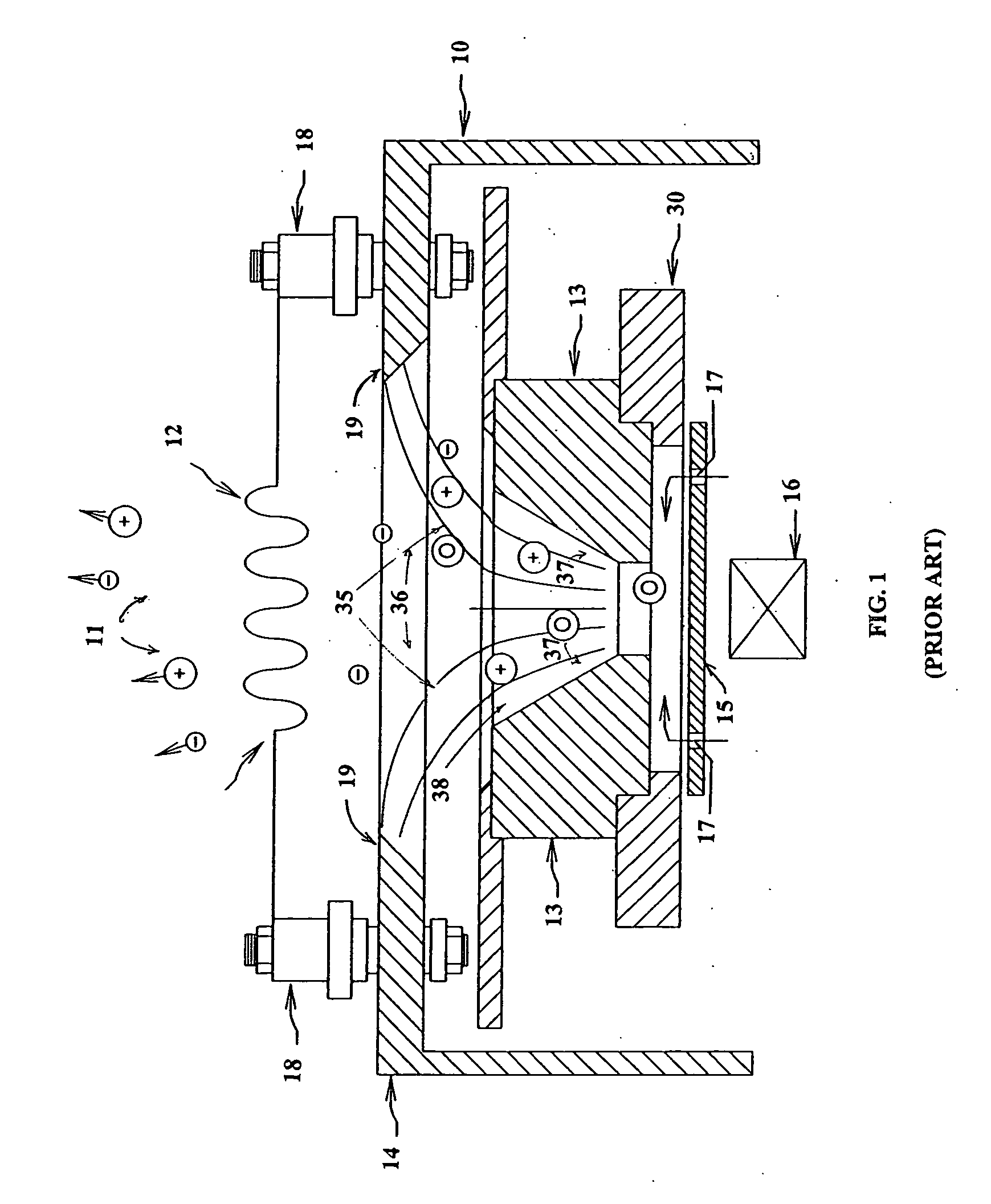
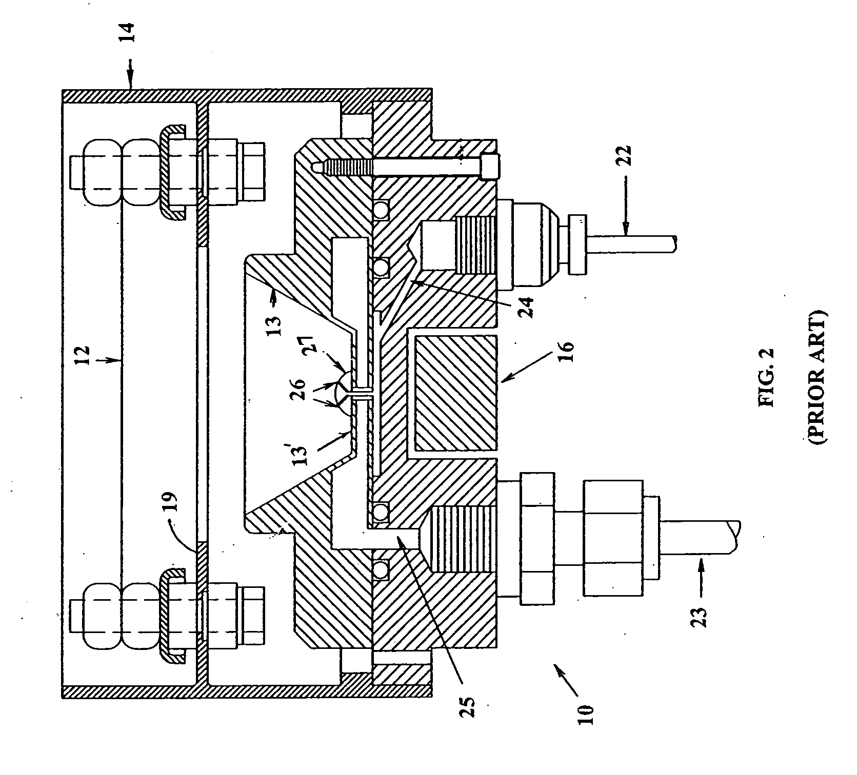
In many cases, instead of a hot filament there is utilized a hollow cathode, which in design is not so simple as a hot filament, but can provide higher emission currents and much longer lifetime.
However, when a hollow cathode (on Argon) utilized with reactive gases such as Oxygen in anode area, its lifetime becomes shorter due to penetration of reactive gases into a hollow cathode area that becomes “poisoned” (oxidized) with reactive gases.
Such strong plasma flow leads into a severe damage of a gas distributor / reflector, 15 reducing its lifetime significantly.
Besides a gas distributor / reflector damage, its sputtered particles fly back into a discharge channel's exit, into a vacuum chamber area leading into contamination of an etching / deposition process involving ion source.

Method used


Image

  • High-efficient ion source with improved magnetic field
  • High-efficient ion source with improved magnetic field
  • High-efficient ion source with improved magnetic field

Examples


Embodiment Construction

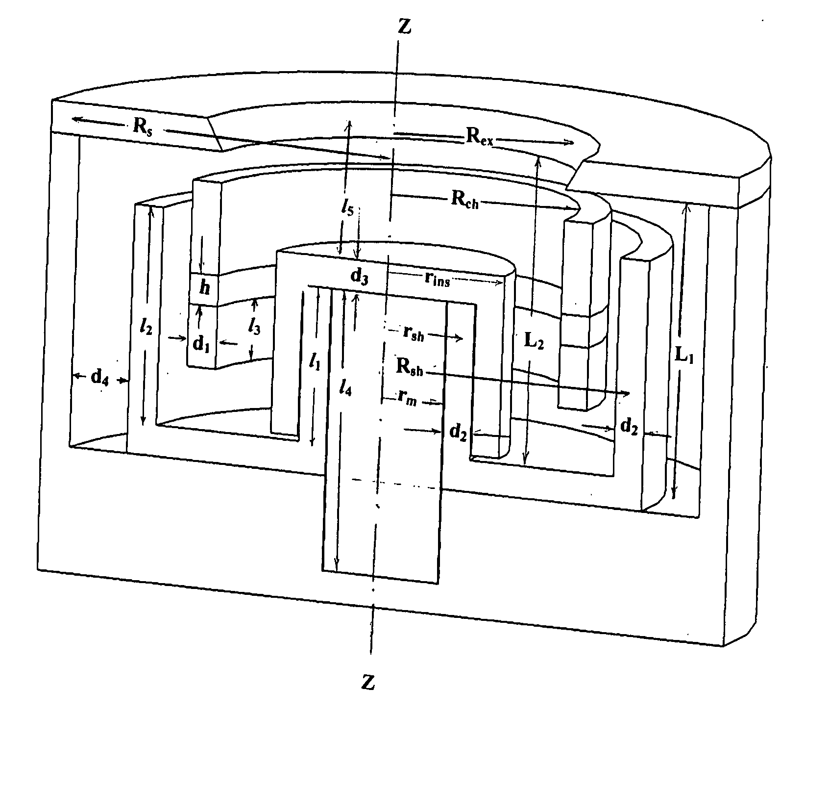
[0061]FIG. 4 presents a schematic drawing of the invented Hall-current ion source 10 with a hybrid discharge channel consisting of a protruding central magnetic pole 44 and an external cylindrical wall 46, 47, 48. Axis of symmetry is a line Z-Z. An internal cylindrical discharge channel wall, 42 made of dielectric material. The cylindrical external wall parts 46, 48 can be made either from a dielectric material typically out of Boron Nitride, as all existing closed drift thrusters with magnetic layer, or out of a conducting material typically out of stainless steel or copper. A discharge channel with external cylindrical wall made of ceramic material has anode 37 placed at bottom part of discharge channel at certain distance from a gas distributing system 39 (shown holes for working gas application).

[0062] A discharge channel with external cylindrical wall made of a conducting material consists of three parts: upper part 46, anode 37, and bottom part 48. Parts 46 and 48 are under a...


PUM


Abstract

A Hall-type ion source for generation of ion beams for technological applications presents itself a hybrid ion source, where properties of closed drift systems and end-Hall ion sources are combined for more efficient operation. An ion source has shorter central magnetic pole than regular closed drift ion source with magnetic screens that provide positive magnetic gradient in an ion source's discharge channel. An ion source with these combined properties has higher ratio of ion beam current to discharge current than end-Hall ion source and wider range of discharge parameters than closed drift ion source.

Description

CROSS-REFERENCE TO RELATED APPLICATION [0001] This application is based upon, and claims the benefit of Provisional Application No. 60 / 565,115 filed on Apr. 23, 2004.BACKGROUND OF THE INVENTION [0002] 1. Field of the Invention [0003] This invention relates generally to technology of ion and plasma sources, and more particularly to Hall-type ion sources producing high-current ion beams that can be utilized in thin film processing technology. Historically, thrusters, or accelerators of ions were utilized for space application to move, or stabilize space satellites since early 70-ies. Ion sources that can be considered a spin-off of electric propulsion thrusters have the same operational principles. However, they do not need to be light and efficient as thrusters; they need to accelerate ions, produce high ion beam currents with regulated ion beam mean energy, be efficient in vacuum etching, deposition, in assisting to certain physical processes involving interaction of sputtered parti...

Claims


Application Information

Patent Timeline
IPC IPC(8): H01J7/24H01J27/14
CPCH01J27/146H01J27/143
Inventor ZHURIN, VIACHESLAV V.
Owner ZHURIN VIACHESLAV V
Learn More