Increased capacity sulfur recovery plant and process for recovering elemental sulfur

a sulfur recovery plant and increased capacity technology, applied in the direction of sulfur preparation/purification, energy input, teeth capping, etc., can solve the problems of reducing the capacity of the plant, reducing the conversion rate of 70 %, and improving the recovery almost invariably

Active Publication Date: 2009-03-10
PHILLIPS 66 CO
View PDF100 Cites 31 Cited by
  • Summary
  • Abstract
  • Description
  • Claims
  • Application Information

AI Technical Summary

Benefits of technology

[0017]New Claus sulfur recovery plants and improved existing Claus installations are disclosed which contain one or more compact tubular Claus reactor-heat exchanger unit (sometimes referred to herein as the “tubular Claus catalytic reactor” or simply “TClaus reactor”). In some instances, these new or modified Claus plants are additionally improved by including one or more compact heat exchangers comprising cooling tubes that are filled with a heat transfer enhancement medium. Methods of using the new or modified Claus plants, Claus catalytic reactors, heat exchangers and sulfur condensers, are also disclosed. Various embodiments of the present invention make it possible to overcome many of the drawbacks that are inherent in many sulfur recovery plants and processes for recovering sulfur from H2S-containing gases by providing apparatus or methods for increasing the sulfur recovery capacity of new and existing Claus operations. New high-capacity modified Claus plants and methods of constructing and operating such plants at lower cost than conventional sulfur recovery installations are now made possible.
[0019]In accordance with some embodiments of the present invention a compact, high efficiency heat exchanger, such as a waste heat exchanger or sulfur condenser having cooling tubes filled with a heat transfer enhancement medium (HTEM), is provided. In certain embodiments, the HTEM-containing heat exchanger is included in an above-described new or modified Claus plant as a way to further increase the capacity of the plant and to reduce its overall size.
[0029]Further improvements to a sulfur recovery plant are provided by employing one or more HTEM-containing heat exchanger to lower the heat exchange area requirement and / or to provide improved sulfur coalescence on HTEM over a wider mass velocity operating range. For example, HTEM in the reaction furnace waste heat boiler allows for a shorter or smaller diameter boiler by reducing the heat transfer area required. In a conventional Claus reactor assembly, the use of HTEM in each sulfur condenser allows for reducing the heat transfer area of the outer tube and helps coalesce the sulfur condensed to prevent having aerosol or entrained sulfur leave that stage of the assembly. This in turn, improves the performance of a subsequent Claus catalyst bed.
[0037]In some embodiments of an above-described process, the heat transfer fluid inlet is disposed nearer to the last group of concentric tubular reactor assemblies than to the other or earlier (preceding) groups of reactor assemblies, the interior fluid space comprises a baffle disposed between the last group of reactor assemblies and the earlier groups of reactor assemblies, and the heat transfer fluid comprises water, and step (d) further comprises introducing pressurized water into the fluid inlet, wherein the pressurized water is at a temperature in the range of about 100-125° C., to cool the process gas and condensed sulfur from the last group of reactor assemblies to a lower temperature than that of the process gas and condensed sulfur from the earlier reactor assemblies, whereby the overall sulfur recovery of the process is enhanced.
[0039]A compact, tubular Claus catalytic reactor-heat exchanger combination unit offers advantages over most other ways that are currently used to expand the total capacity of a new or existing Claus sulfur recovery plant. Employing a new TClaus reactor, as described herein, requires minimal new equipment. In some instances, its use can eliminate altogether the need for construction of a new plant. Use of a new TClaus reactor does not require revision of the liquid sulfur seal devices on the existing unit. Using the new reactor generally does not require raising the operating pressure of the feed-producing units. A process that employs the new catalytic Claus reactor does not require the substitution of costly oxygen for air. With the new catalytic Claus reactor, alloy construction for oxygen transport lines and instruments is not necessary. Additionally, when the new catalytic Claus reactor is employed, it does not affect the free flame combustion chamber temperature. As a result, the need for temperature moderation for high level O2 (typically 30%) in the combined air / oxygen stream is eliminated. These and other embodiments, features and advantages of the present invention will become apparent with reference to the following description and drawings.

Problems solved by technology

A 70% level of conversion is insufficient by today's standards to allow the effluent from the Claus furnace to be emitted to the atmosphere or to make tail gas treatment economical at this point.
The addition of equipment needed to improve recovery almost invariably decreases the capacity of the plant by adding resistance to flow from additional friction.
In almost every case, a conventional sulfur recovery plant with a burner, reaction furnace, single catalytic Claus reactor, and single tail gas treatment unit is limited to 5 to 15 psi of available pressure drop.
Many existing Claus plants suffer from a severe constraint in capacity.
A drawback of the latter approach is that the SO2 feed must provided in addition to the H2S feed.
Another downside of directly contacting a Claus conversion catalyst with the acid gas feed stream is that serious negative consequences can result when the H2S stream contains certain additional components.
In the case of hydrocarbon and ammonia contaminants, for example, incomplete destruction of ammonia and incomplete combustion of hydrocarbon typically occur, leading to ammonia salt plugging, and sooting (coke deposition).
The difficulty of replacing underground sulfur sealing devices and the poor operation of feed-producing units at higher pressure usually limits the gains that can be realized from this latter approach.
The economic appeal of oxygen enrichment is limited by the cost of the oxygen, the temperatures attained in an O2-enriched flame, and by the cost of the special equipment needed to handle high concentrations of oxygen.
Efforts to redesign the system for low pressure drop have generally met with little success, since each piece of equipment must be designed for low pressure drop and the total number of pieces of equipment in a Claus Plant, there is only a small amount of pressure drop available for the entire plant.
A low heat transfer coefficient prompts an increase in the heat exchange areas in the design, usually by lengthening the tubes of the heat exchanger, with an associated increase in pressure drop due to the increased friction from the longer tubes.
While greater shell diameters and an increased number of tubes could be used to overcome the pressure drop restriction, those remedies tend to greatly increase the cost of heat exchanger construction compared to merely lengthening the existing number of tubes.
The larger diameters and limits on tube mass velocities generally lead to undesirably low heat transfer coefficients.
The efficiency of any sulfur condenser is inherently limited by the properties of elemental sulfur.
Designing a higher-capacity Claus plant is also complicated by the size and number of Claus catalytic reaction units that are customarily used today, each including a sulfur condenser with coolant system, reheater, and Claus conversion catalyst.
The nominal design GHSV of a Claus catalytic reactor can make the catalyst volume requirements quite large.
Combining the design elements of multiple reheat, reaction and condensation stages with the GHSV requirements for a typical Claus reactor leads to very large, expensive units.

Method used


Image

  • Increased capacity sulfur recovery plant and process for recovering elemental sulfur
  • Increased capacity sulfur recovery plant and process for recovering elemental sulfur
  • Increased capacity sulfur recovery plant and process for recovering elemental sulfur

Examples


Embodiment Construction

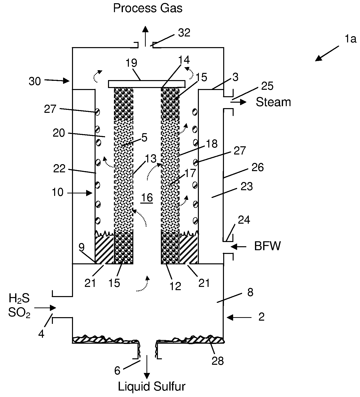
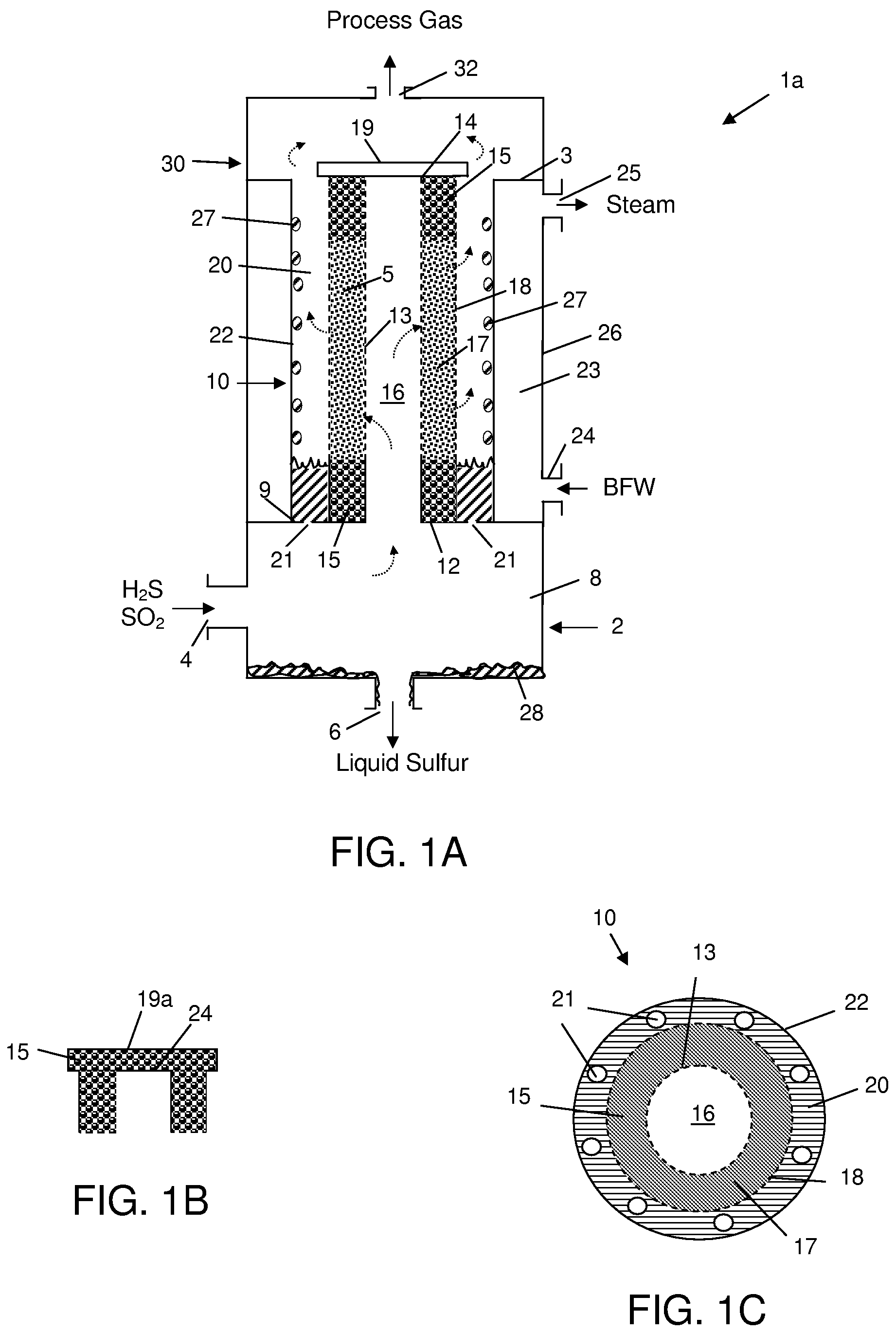
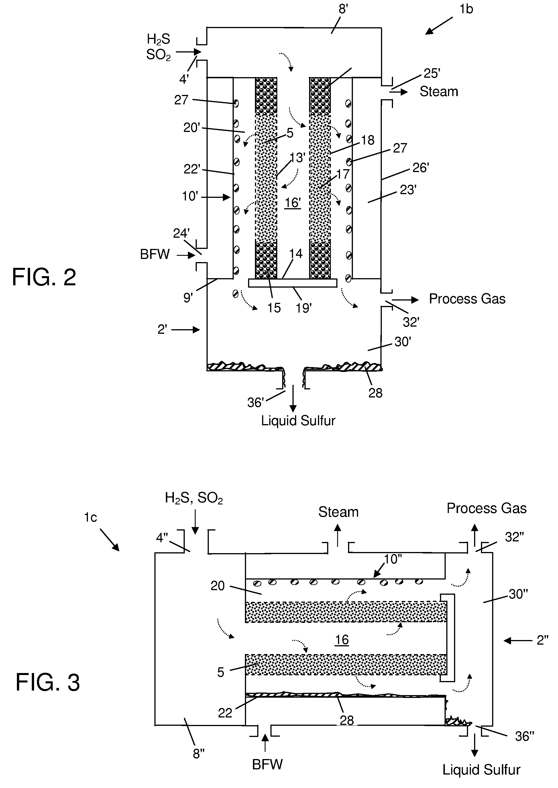
[0056]An improved Claus sulfur recovery plant contains one or more single-stage or multi-stage compact tubular Claus catalytic reactor units. These new or improved Claus plants may be additionally improved by inclusion of one or more compact heat exchangers containing cooling tubes that are filled with a heat transfer enhancement medium.

Compact, Tubular Claus Catalytic Reactor Units.

[0057]Toward decreasing the cost and complexity of the catalytic section of a Claus sulfur recovery plant, a study of the kinetics of the Claus reaction (Equation 3) was conducted, and the experimental data is shown in Table 1. Various parameters that were computed from the data are listed in Table 2, including estimated catalyst volumes required in each stage of a Claus plant in order to produce about 108 long tons per day (LTPD) of sulfur. From this study it was determined that the catalyst volumes actually required are much smaller than the conventionally designed volumes, e.g., about 434 cu ft of cat...


PUM

PropertyMeasurementUnit
temperatureaaaaaaaaaa
pressure dropaaaaaaaaaa

Abstract

Claus sulfur recovery plants that include one or more single-stage or multi-stage compact tubular Claus catalytic reactor-heat exchanger units are disclosed. In some instances, these new or improved Claus plants additionally include one or more compact heat exchanger containing cooling tubes that are filled with a heat transfer enhancement medium. The new compact tubular Claus catalytic reactor-heat exchanger units and HTEM-containing heat exchangers are also disclosed. A process for recovering sulfur from a hydrogen sulfide-containing gas stream, employing the new tubular Claus catalytic reactor-heat exchanger unit, and in some instances a HTEM-containing heat exchanger, are also disclosed.

Description

BACKGROUND OF THE INVENTION[0001]1. Technical Field of the Invention[0002]The present invention generally relates to methods and apparatus for recovering elemental sulfur from hydrogen sulfide-containing gas streams, and more particularly to such methods and apparatus that increase the sulfur recovery capacity of new or existing Claus plants and reduce the size and complexity of such plants.[0003]2. Description of Related Art[0004]Large quantities of H2S-containing gases are commonly produced in the petrochemical industry by amine treating units and sour water stripping units. Claus sulfur recovery plants (“Claus plants”) are in widespread use to convert this environmentally hazardous H2S to useful elemental sulfur by oxidation according to the overall or net equationH2S+½O2→1 / xSx+H2O  (1)wherein x=2, 6 or 8, depending on the particular conditions of temperature and pressure. The net production of elemental sulfur is usually accomplished as a series of process steps carried out acco...

Claims


Application Information

Patent Timeline
Patent Type & Authority Patents(United States)
IPC IPC(8): C01B17/04B01J12/00B01J12/02B01J19/00
CPCC01B17/0439C01B17/0447C01B17/0469F28D7/103Y10S165/913Y10S423/06Y02P20/129
Inventor KELLER, ALFRED E.RAMANI, SRIRAMALLISON, JOE D.LUSK, STEVEN E.HATCHER, NATHAN A.SWINNEY, LARRY D.SHAVER, REBECCA S.
Owner PHILLIPS 66 CO
Why Eureka
Try Eureka