Reactor distribution apparatus and quench zone mixing apparatus

a technology of distribution apparatus and reaction vessel, which is applied in the direction of physical/chemical process catalysts, furnaces, separation processes, etc., can solve the problems of undesirably high pressure drop, complicated devices, and easy plugging, and achieve the effect of reducing the overall vertical height of the reaction vessel, reducing the capital cost of the vessel, and reducing the overall vertical height of the quench zone mixing apparatus

Inactive Publication Date: 2002-01-15
FLUOR TECH CORP
View PDF5 Cites 30 Cited by
  • Summary
  • Abstract
  • Description
  • Claims
  • Application Information

AI Technical Summary

Benefits of technology

As noted above, the quench zone mixing apparatus includes a swirl chamber. The swirl chamber is adapted to receive fluids from upstream in the reactor (such as those exiting a catalyst bed located above the swirl chamber). Preferably, the swirl chamber is substantially cylindrical. The swirl chamber includes a wall disposed between a ceiling and a floor. The wall has a plurality of openings, such as inlet openings, that provide a means of fluid communication into the swirl chamber. The floor surrounds an orifice, which provides a means for fluid to exit the swirl chamber. Preferably, a weir is provided about the periphery of the orifice. Baffles are located inside the swirl chamber which stabilize the vapor and liquid phase vortices, reduce the required overall height of the swirl chamber, provide a wide operating range for vapor and liquid throughput, and promote turbulence / mixing within each of the fluid phases. At least some of the openings have a baffle associated with the openings.
In a preferred embodiment, a first set of radial beams having a single vertical height is used to support the swirl chamber and distribution channels. Additionally, a support ring is attached to the outside wall of the swirl chamber at a location just below the inlet openings. A second support ring is attached to the vessel wall at a location approximately equal to the elevation of the swirl chamber ceiling. The liquid collection tray is provided on top of the support rings in the area between the vessel wall and the swirl chamber to preferably create a frusto-conical shape that directs fluids from the catalyst bed above toward the swirl chamber inlet openings. The ring at the wall provides support for the liquid collection tray and a sealing surface to prevent fluids from bypassing the swirl chamber.
As pointed out in greater detail below, the quench zone mixing apparatus of this invention provides important advantages. The design of the invention apparatus minimizes the overall vertical height of the quench zone mixing apparatus. As a result, the overall vertical height of the reaction vessel can be decreased, thereby reducing the capital cost of the vessel. At the same time, intimate mixing and thermal equilibration is achieved while maintaining only a moderate pressure drop across the device.

Problems solved by technology

Some of these devices are complicated and are prone to plugging.
Still others create an undesirably high pressure drop.

Method used


Image

  • Reactor distribution apparatus and quench zone mixing apparatus
  • Reactor distribution apparatus and quench zone mixing apparatus
  • Reactor distribution apparatus and quench zone mixing apparatus

Examples


Embodiment Construction

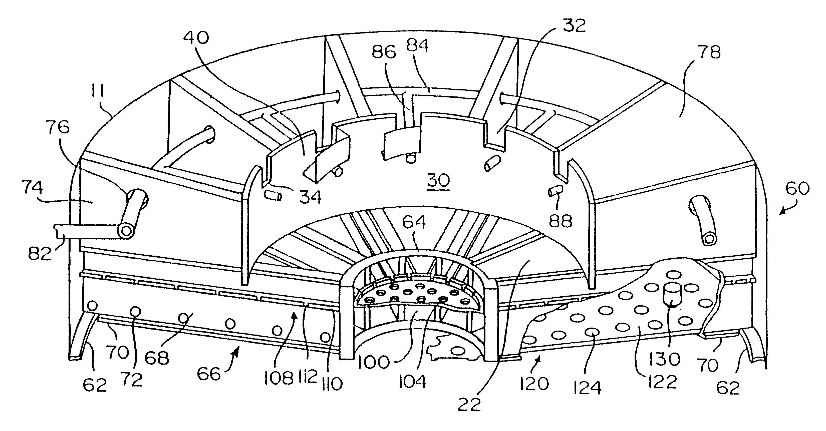
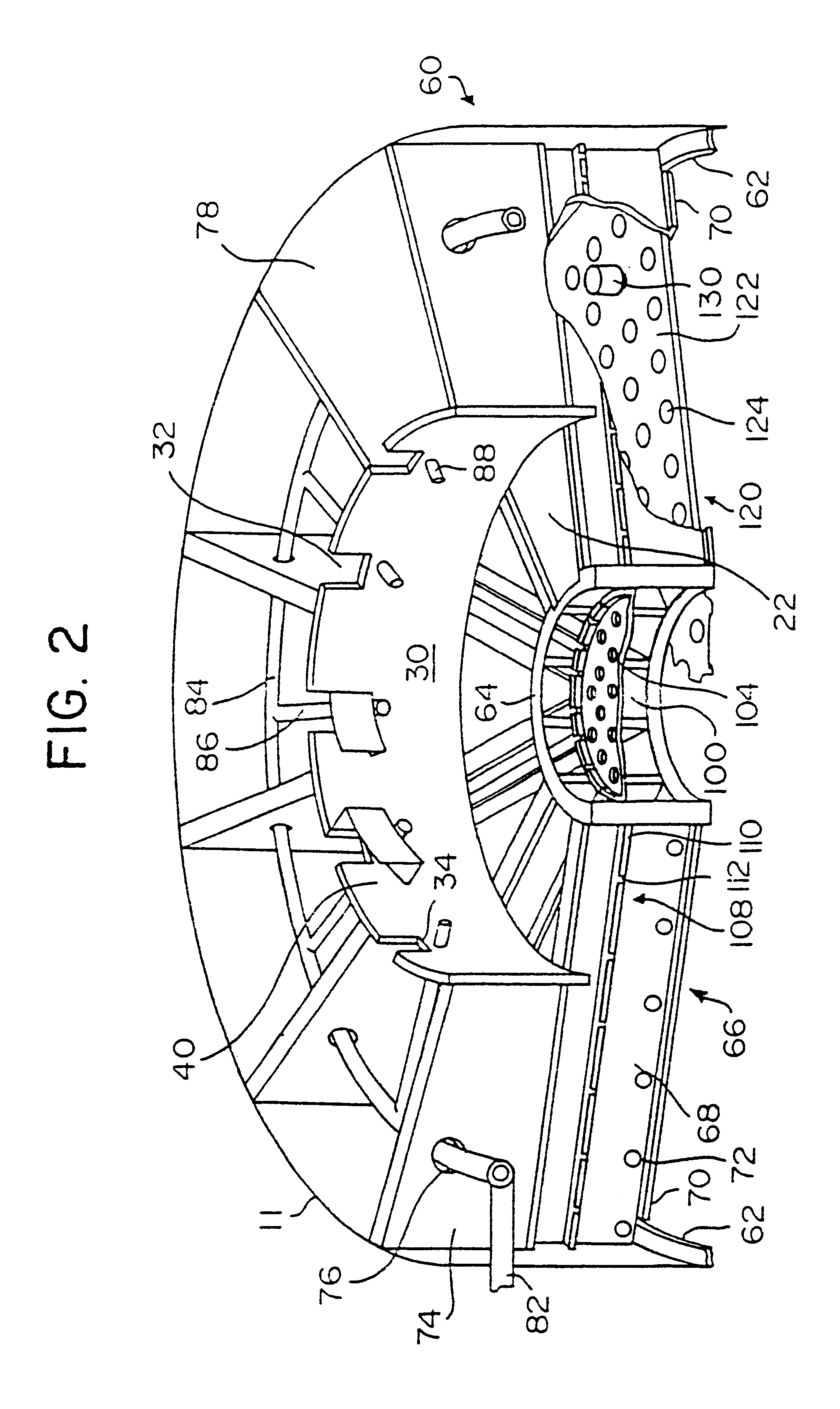
The quench zone mixing apparatus invention will now be described with reference to its use in a multi-bed, catalytic reactor in which the apparatus is located in a zone between two catalytic beds. It is understood by one skilled in the art that the apparatus of the present invention can also be used in non-catalytic vessels or reactors.

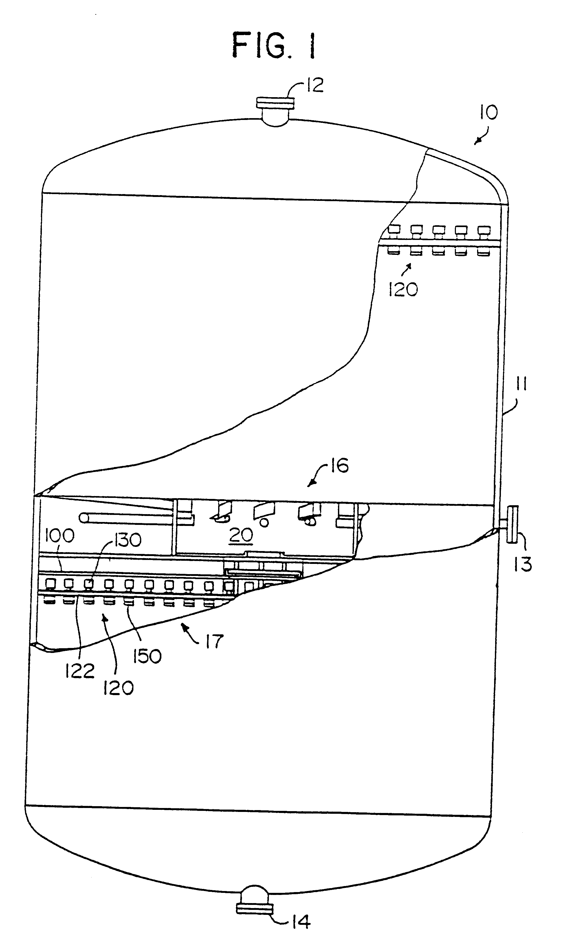
As shown in FIG. 1, the reactor 10 comprises a cylindrical vessel. While the vessel is preferably substantially cylindrical, it can also have any shape that is suitable for manufacturing concerns. The vessel is typically constructed of corrosion resistant metal or an equivalent material such as stainless steel, weld overlayed chrome alloy steels, or the like. The vessel is normally insulated internally or externally for operation at elevated temperatures.

Typically, an inlet 12 is provided in the vessel at its top portion for convenience in filling the vessel with catalyst, for routine maintenance, or for flow of fluid, as dictated by the particular ap...


PUM

PropertyMeasurementUnit
lengthsaaaaaaaaaa
diametersaaaaaaaaaa
pressureaaaaaaaaaa

Abstract

A quench zone mixing apparatus is supported within a vessel of a reactor by a support structure that includes a concentric hub, which may be formed to act as a torsion tube, and at least a first set of radial beams extending radially outward from the hub and terminating at a support ring that is attached to the reactor vessel wall. In particular, the radial beams comprise a flange that supports the redistribution tray and a web of the beams preferably includes a plurality of openings to allow the passage of fluids across the vessel. In addition, the webs also carry the channels. The radial beams also support the mixing chamber and, in the area between the wall of the mixing chamber and the vessel wall, the radial beams may have a vertical height that slopes downward from the vessel wall to the mixing chamber wall.

Description

1. Field of the InventionThe present invention relates to a distribution apparatus and a quench zone mixing apparatus (or device) that may include the distribution apparatus, both of which are suitable for efficiently mixing and redistributing reactants across the horizontal cross-section of a vertical reaction vessel.2. Discussion of Related ArtMany catalytic processes are carried out in reactors that contain a series of separated catalytic beds. Frequently, in such processes, quench zone mixing devices are advantageously located to provide rapid and efficient mixing of the fluid streams being processed in the reactor with a cooler fluid stream supplied from an external source. Consequently, the temperature of the process stream entering the successive catalyst beds can be controlled. One skilled in the art will appreciate that the better the mixing of the reactant streams, the better the temperature and reaction can be controlled. As a result, the overall performance of the reacto...

Claims


Application Information

Patent Timeline
Patent Type & Authority Patents(United States)
IPC IPC(8): B01J8/04B01J8/02B01F5/00B01D3/14B01F5/06B01D3/20B01D47/16B01F23/00B01D47/00B01J2/00B01J10/00B01J35/02C10J1/08F02M17/28F02M29/04
CPCB01D3/20B01F5/0057B01J8/0278B01J8/0492B01F5/0618B01J2208/00353B01F25/10B01F25/4316
Inventor STUPIN, STEVEN W.JACOBS, GARRY E.NELSON, DOUGLAS E.KUSKIE, ROBERT W.BINGHAM, F. EMMET
Owner FLUOR TECH CORP
Why Eureka
Try Eureka