Connector, and LED lighting apparatus using the connector

Inactive Publication Date: 2012-01-26
KYOCERA CONNECTOR PRODS CORP
View PDF8 Cites 12 Cited by
  • Summary
  • Abstract
  • Description
  • Claims
  • Application Information

AI Technical Summary

Benefits of technology

[0031]According to the present invention, when a positional deviation occurs between the circuit board and the connecting object adjacent to each other in the elongated direction of the plug contact, this positional deviation is absorbed by a slide movement of the contact portion of the plug contact with respect to the pair of holding portions of the receptacle contact in the elongated direction of the plug contact. Therefore, even if a positional deviation occurs between the circuit board and the connecting object adjacent to each other in the elongated direction of the plug contact, the circuit board and the connecting object can be electrically connected to each other with reliability.
[0032]In addition, the plug contact is a plate-shaped member elongated in one direction which includes no protrusions extending in directions orthogonal to this one direction, thus having a low-profile structure. Accordingly, this low-profile structure makes it possible to achieve a reduction in height of the entire part of the connector.
[0033]Since the plug contact according to the present invention is a substantially straight plate-shaped member having a structure such that the contact portion and the supported portion thereof are aligned, the plug contact has a high mechanical strength against twisting, and the like (compared to a protrusion formed to protrude from a plug contact body). Moreover, stress applied to the plug contact due to a resilient deformation thereof can be effectively dispersed since the plug contact has no bent portion. In addition, since the contact portion, which forms part of the plug contact, is made to be brought in

Problems solved by technology

Additionally, the pair of legs of each plug contact are lower in mechanical strength than the associated columnar connecting portion; however, since the pair of legs of each plug contact are made to contact (to be engaged with) the associated receptacle contact (the pair of resilient lugs thereof) in Patent Document 1, there is a possibility of each leg of each plug contact being distorted or damaged when the pair of legs of each plug contact and the associated receptacle contact are brought into contact with (are connected to) each other with a positional deviation therebetween.
In addition, since the connector disclosed in Patent Document 1 is structured such that one or more legs of each plug contact rotate if the associated adjacent circuit boards deviate from each other in the lateral or rotational direction, repetitive positional deviations or vibrations applied to the connector causes the legs of each plug contact and the pair of resilient lugs of the associated receptacle contact to vi

Method used


Image

  • Connector, and LED lighting apparatus using the connector
  • Connector, and LED lighting apparatus using the connector
  • Connector, and LED lighting apparatus using the connector

Examples


first embodiment

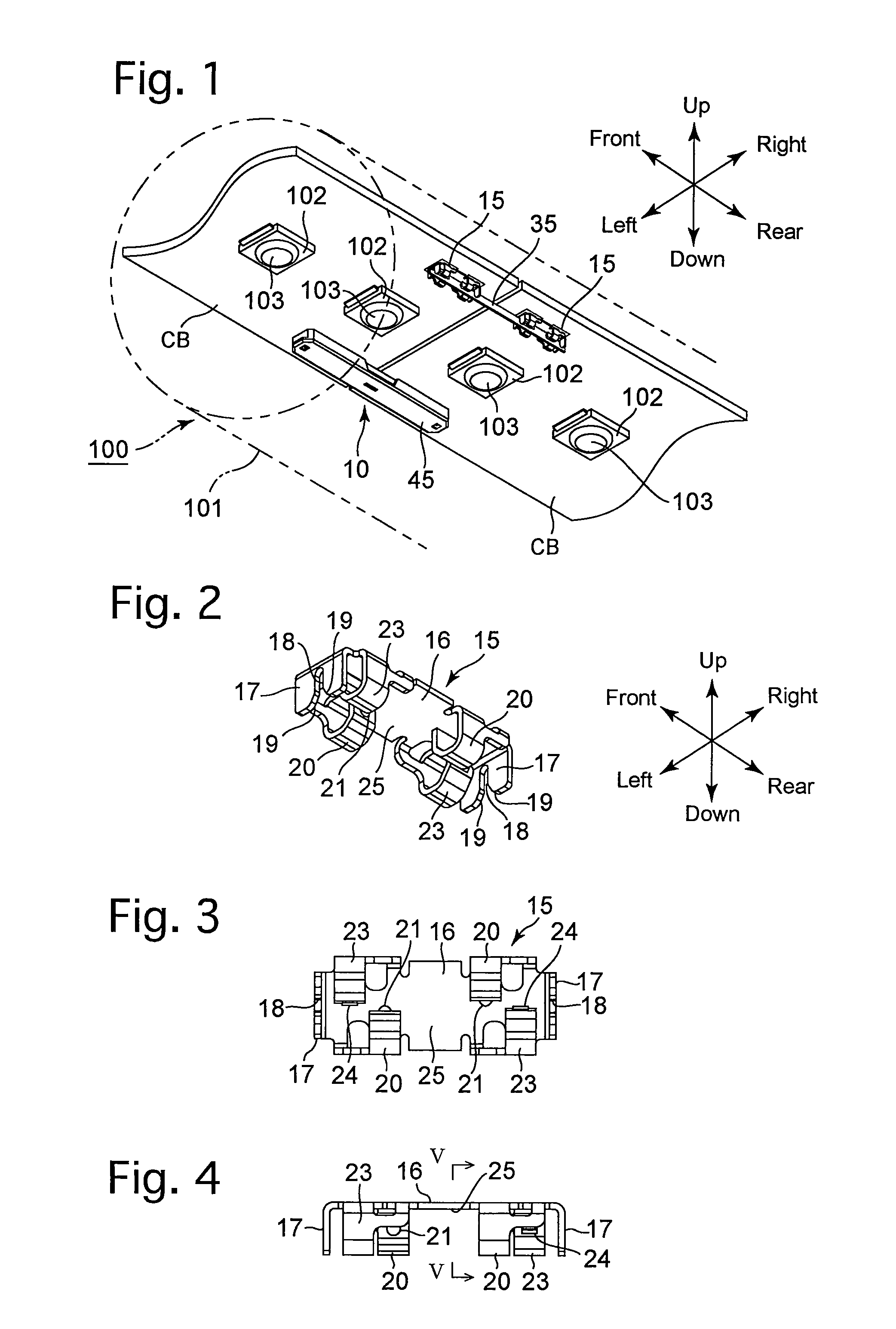
[0067]a straight tube LED lighting apparatus according to the present invention will be hereinafter discussed with reference to FIGS. 1 through 16. In the following descriptions, forward and rearward directions, leftward and rightward directions, and upward and downward directions (vertical direction) of the LED lighting apparatus are determined with reference to the directions of the double-headed arrows shown in the drawings (front, rear, left, right, up and down, respectively).

[0068]The LED lighting apparatus 100 that is shown in FIG. 1 is provided with a translucent tube 101 (only a part of which is shown by two-dot chain lines in FIG. 1), a plurality of circuit boards CB (only two of which are partly shown in FIG. 1), LED units 102 and a plurality of connectors 10. The translucent tube 101 extends linearly in the forward / rearward direction. The plurality of circuit boards CB are arranged inside the translucent tube 101 to lie in a common plane and aligned in the forward / rearwar...

second embodiment

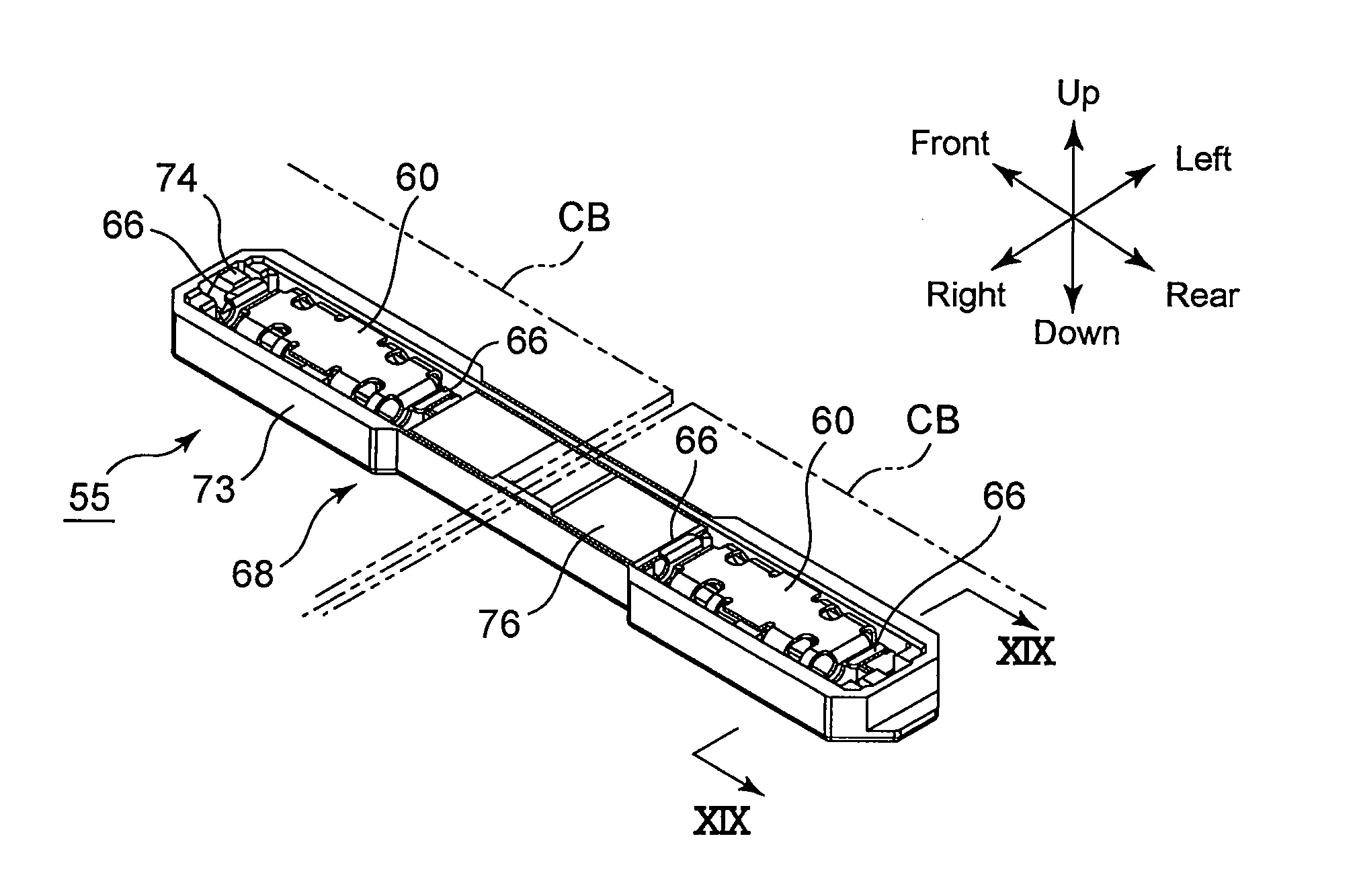
[0129]In a similar procedure to the straight tube LED lighting apparatus, a pair of (left and right) receptacle contacts 60 (only one of which is shown in FIG. 25) are fixed to the undersurface (circuit formation surface) of an end (partly shown by two-dot chain lines in FIG. 25) of the circuit board CBT in the forward / rearward direction which is on the opposite side of the circuit board CBT from the other end thereof that faces the adjacent circuit board CB (not shown in FIG. 25).

[0130]The connector 80 is provided with a receptacle contact 60 and a plug connector 82 which is composed of a plug contact 83 and a plug insulator 88.

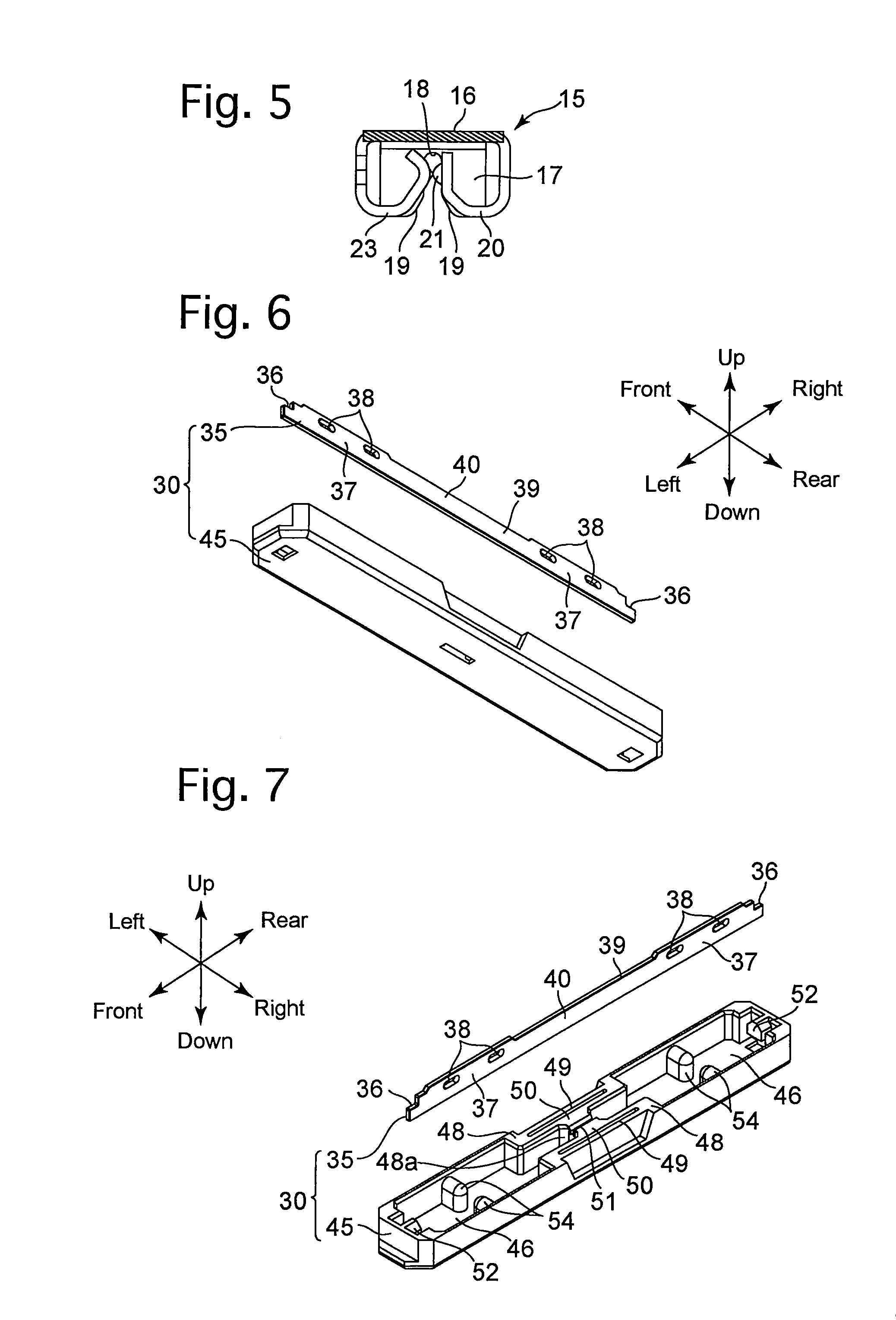
[0131]The plug contact 83 is provided with an engaging recess 36, a contact portion 37 (having a pair of connecting holes 38), a wire connecting strip 84, a retaining lug 85 and a pair of lock-engaging holes 86 (lock portions) (note that the functions of the engaging recess 36, the contact portion 37 and the pair of connecting holes 38 are the same as those ...


PUM


Abstract

A connector includes a plug connector and a receptacle connector which connect a circuit board to a connecting object and allow relative movement therebetween in a common plane or in mutually parallel planes. The receptacle connector includes a receptacle contact including a pair of holding portions and a pair of guide portions which are spaced from each other with the pair of holding portions positioned therebewteen, wherein each guide portion includes a support groove. The plug connector includes a plug contact and a plug insulator which holds the plug contact. The plug contact is linearly elongated and resiliently deformable in a direction of thickness thereof and includes a contact portion that is engaged in the support grooves of the pair of guide portions. The plug insulator includes an opening facing the circuit board, and an accommodation space for accommodating the receptacle contact and the plug contact.

Description

CROSS REFERENCE TO RELATED APPLICATION[0001]The present invention is related to and claims priority of the following co-pending application, namely, Japanese Patent Applications Nos. 2010-165821 filed on Jul. 23, 2010, and 2010-271671 filed on Dec. 6, 2010.BACKGROUND OF THE INVENTION[0002]1. Field of the Invention[0003]The present invention relates to a connector which connects a circuit board and a connecting object while allowing the circuit board and the connecting object to move relative to each other either in a common plane, in which the circuit board and the connecting object both lie, or in mutually parallel planes, in which the circuit board and the connecting object respectively lie, and relates to an LED lighting apparatus using the aforementioned connector.[0004]2. Description of the Prior Art[0005]Straight tube LED lighting apparatuses (LED lamps) are usually provided with a translucent tube, a plurality of circuit boards and a plurality of connectors. The translucent t...

Claims


Application Information

Patent Timeline
IPC IPC(8): F21V23/06H01R12/71
CPCF21S4/008F21V23/06H01R35/00H01R12/7082H01R25/162F21Y2101/02F21S4/28F21Y2115/10F21V17/00H01R12/51
Inventor TAMAI, HIDEHARU
Owner KYOCERA CONNECTOR PRODS CORP
Why Eureka
Try Eureka