Holder-mounting structure

a technology of mounting structure and locking arm, which is applied in the direction of electrical equipment, emergency protection devices, coupling device connections, etc., can solve the problems of reducing the service life bending or breaking the locking arm, and unable to ensure the mechanical strength of the locking arm, so as to achieve sufficient mechanical strength and reduce the service life. the effect of reducing the number of screws

Active Publication Date: 2013-04-09
YAZAKI CORP
View PDF9 Cites 7 Cited by
  • Summary
  • Abstract
  • Description
  • Claims
  • Application Information

AI Technical Summary

Benefits of technology

[0016]In view of the above-identified drawbacks, an object of the present invention is to provide a holder-mounting structure that realizes two features that often do not go together, i.e., ensuring sufficient level of mechanical strength and making the product thinner and more low-profile.
[0021]Some objects, features and advantages of the present invention include: providing the low-profile holder-mounting structure; increased mechanical strength of the plate portion; providing the holder-mounting structure that is made low-profiled in the second direction; providing improved mechanical strength of the arm portion; prevention of unstable contact between the holder and the holder mounting portion by virtue of abutment of the arm portion on the outer surface.

Problems solved by technology

However, uniform reduction in the thickness of the locking arms 107, 108 can cause the locking arms 107, 108 to be bent or broken, which makes it difficult to ensure sufficient mechanical strength of the locking arms 107, 108 that have to reliably hold the holder 102.

Method used


Image

  • Holder-mounting structure
  • Holder-mounting structure
  • Holder-mounting structure

Examples


Embodiment Construction

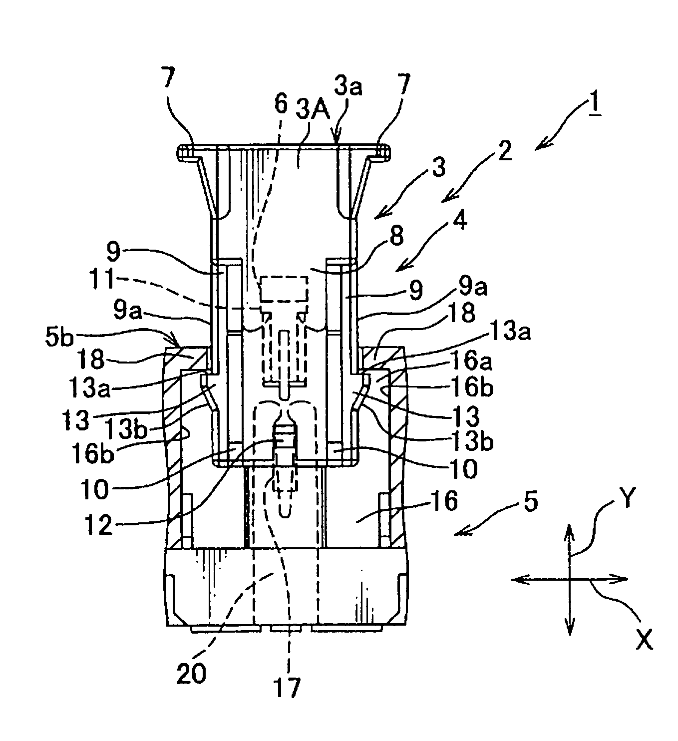
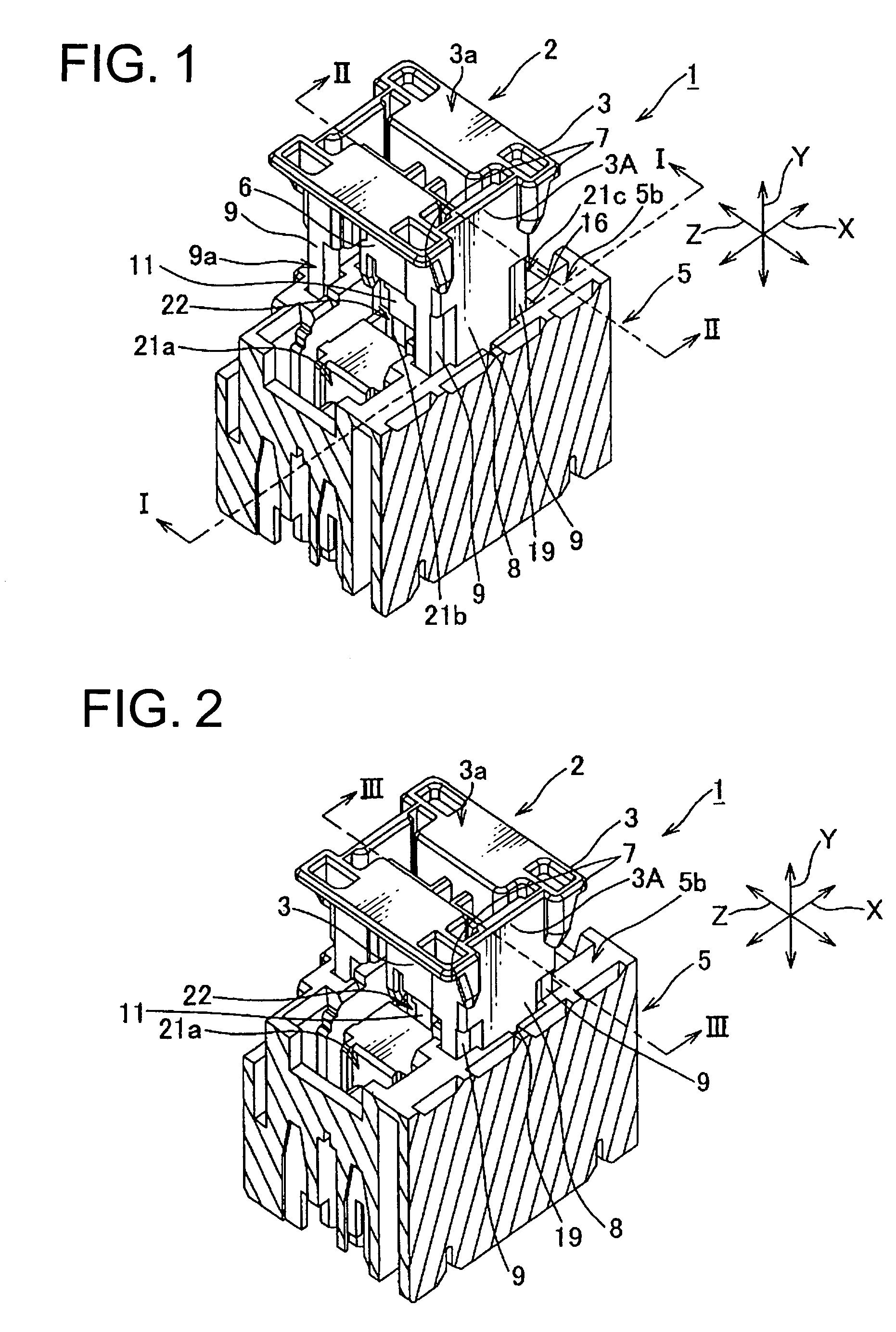
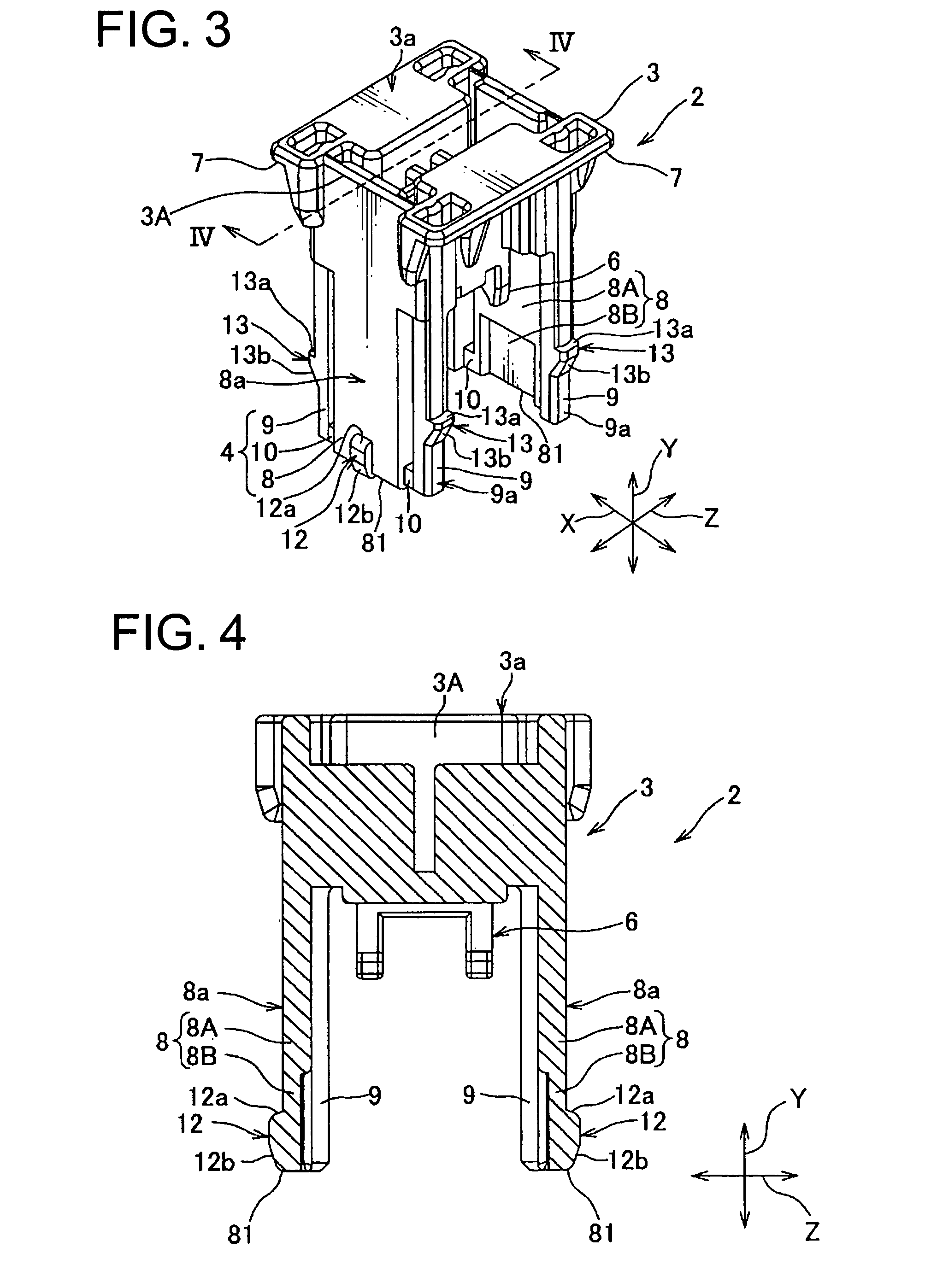
[0034]A holder-mounting structure 1 according to one embodiment of the present invention is described with reference to FIGS. 1 to 8.

[0035]Referring to FIGS. 1 and 2, the holder mounting structure 1 according to this embodiment comprises (A) a holder 2 to which an electric component such as a fuse 11 is attached, and (B) a holder mounting portion 5 that includes an accommodating portion 22 into which the holder 2 is slidably inserted. The holder mounting portion 5 is provided in an electrical junction box disposed in an automobile.

[0036]The fuse 11 may be provided between a dark-current component and a power source and connected to them. The dark-current component may comprise a component having a clock function that has to be kept active even when an ignition is turned off.

[0037]The fuse 11 is connected to and provided between the power source and the dark-current component and adapted to melt down to stop power supply to the dark-current component when an overcurrent from the powe...


PUM


Abstract

A holder-mounting structure comprises a holder and a holder mounting portion into which the holder is slidably inserted. The holder includes a holder body for mounting of an electric component and a pair of plate portions extending from the holder body such that the electric component resides therebetween. The plate portions include a thick-walled portion continuing to the holder body and a thin-walled portion continuing to the thick-walled portion and provided at an end of the plate portion away from the holder body. The holder mounting portion includes an accommodating portion into which a connecting terminal connected to the electric component is accommodated. The thin-walled portion includes a complete-locking portion configured to be brought into locking engagement with the holder at a position where the electric component is connected to the connecting terminal with the holder slidably inserted into the accommodating portion.

Description

CROSS-REFERENCE TO RELATED APPLICATION[0001]This application is related to co-pending application: “COMPONENT-EQUIPPED-HOLDER MOUNTING STRUCTURE” filed concurrently herewith in the names of Makoto Nakayama and Takahiko Mitsui, which application is assigned to the assignee of the instant application and is incorporated by reference herein.[0002]This application claims priority to Japanese Patent Application No. 2010-072776, filed on Mar. 26, 2010, which is incorporated by reference herein.BACKGROUND OF THE INVENTION[0003]1. Field of the Invention[0004]The present invention generally relates to a structure configured for mounting a holder to an electrical junction box, and in particular to a holder-mounting structure configured for mounting a holder, to which an electric component is attached, on a holder mounting portion provided in an electrical junction box.[0005]2. Description of Related Art[0006]FIG. 10 illustrates a conventional holder-mounting structure 101. The holder-mounting...

Claims


Application Information

Patent Timeline
Patent Type & Authority Patents(United States)
IPC IPC(8): H01R13/66
CPCH01H9/042H01H85/045H01H85/54H01H85/20H01H85/22H01H85/147
Inventor NAKAYAMA, MAKOTOMITSUI, TAKAHIKO
Owner YAZAKI CORP
Why Eureka
Try Eureka