Disk chucking mechanism and disk drive device

a technology of chucking mechanism and disk drive, which is applied in the direction of magnetic recording, data recording, instruments, etc., can solve the problems of increasing the axial length of the shank g, affecting the construction of the disk chucking mechanism, and limiting the efforts to reduce the thickness of the support arm n, so as to achieve the effect of low profile and increasing the positional accuracy of various components

Inactive Publication Date: 2005-03-17
SONY CORP
View PDF1 Cites 7 Cited by
  • Summary
  • Abstract
  • Description
  • Claims
  • Application Information

AI Technical Summary

Benefits of technology

[0040] It is therefore an object of the present invention to provide a disk chucking mechanism and a disk drive device which will solve the above problems and have a low-profile structure achieved by increasing the positional accuracy of various components thereof.

Problems solved by technology

However, the conventional disk chucking mechanism a is problematic in that the support arm n has a poor positional accuracy because the holder spring q presses the chucking pulley c against the disk-shaped recording medium w.
However, an increase in the axial length of the shank g presents an obstacle to efforts to construct the disk chucking mechanism a in a low-profile configuration.
However, there is a certain limitation on efforts to reduce the thickness of the support arm n because the support arm n has to have a certain level of rigidity to achieve desired mechanical strength.
Accordingly, the thickness of the chucking pulley c is also increased, and the chucking pulley c moves vertically an increased distance, making it difficult to make the disk chucking mechanism a lower in profile.

Method used


Image

  • Disk chucking mechanism and disk drive device
  • Disk chucking mechanism and disk drive device
  • Disk chucking mechanism and disk drive device

Examples


Embodiment Construction

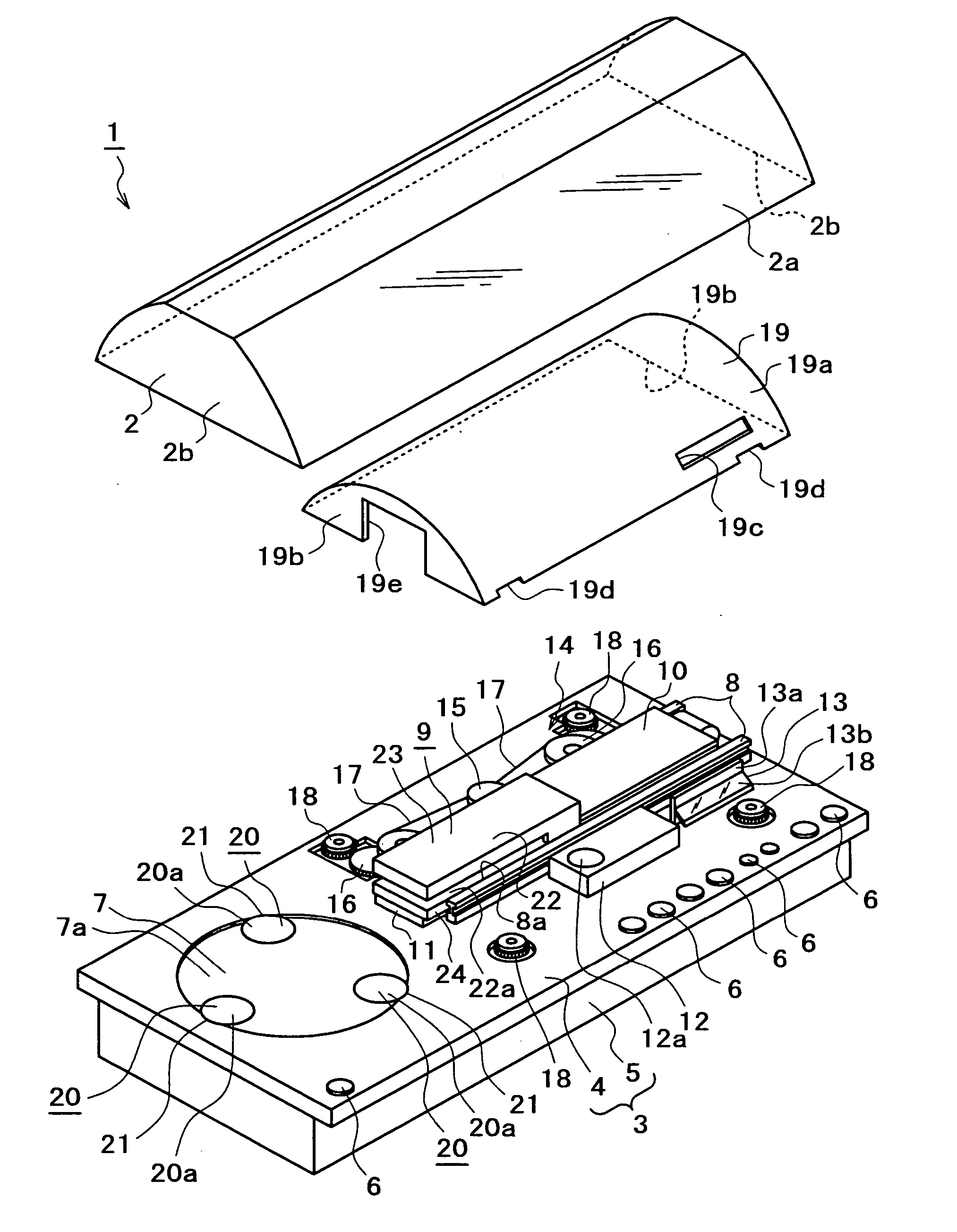
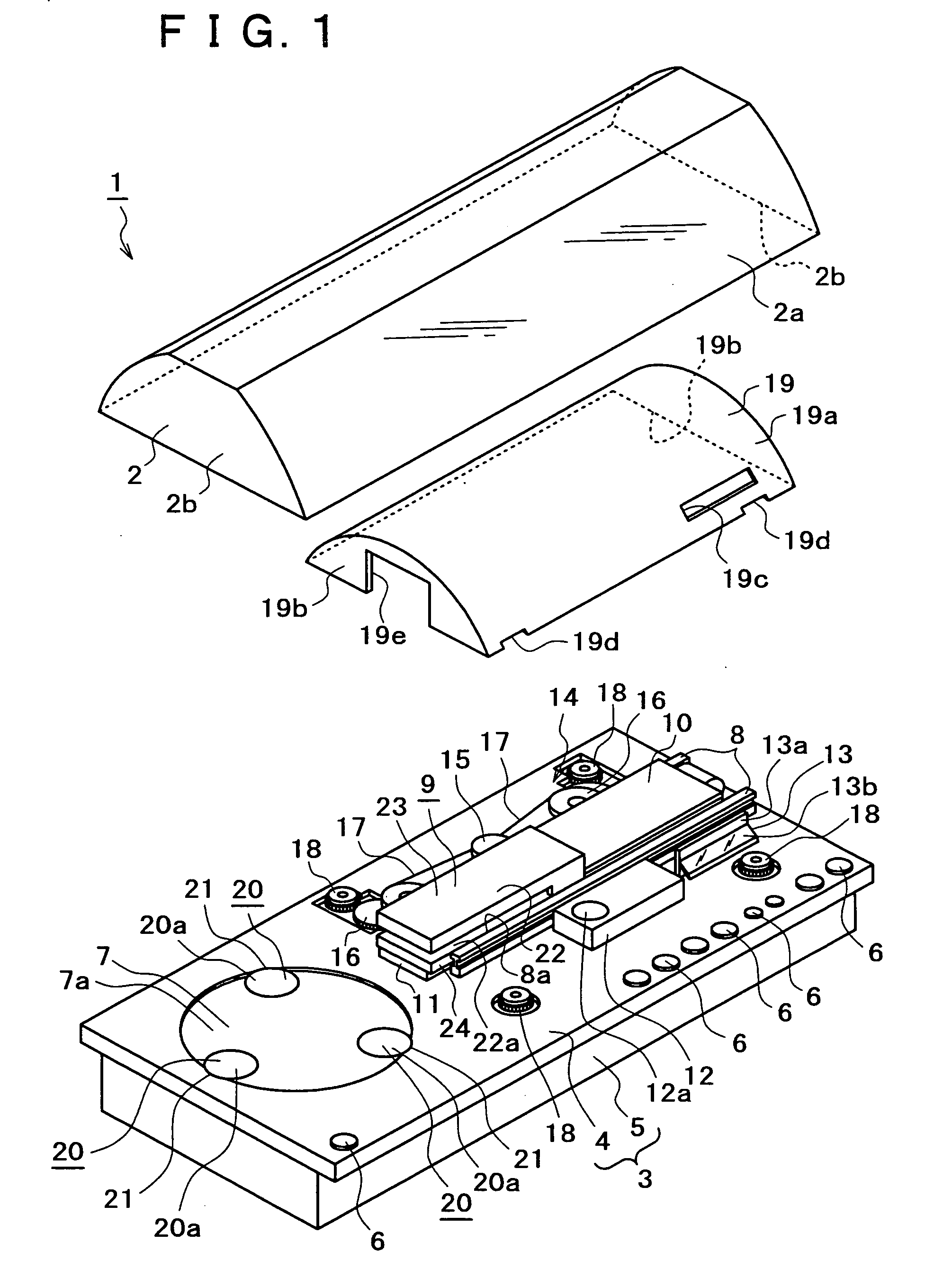
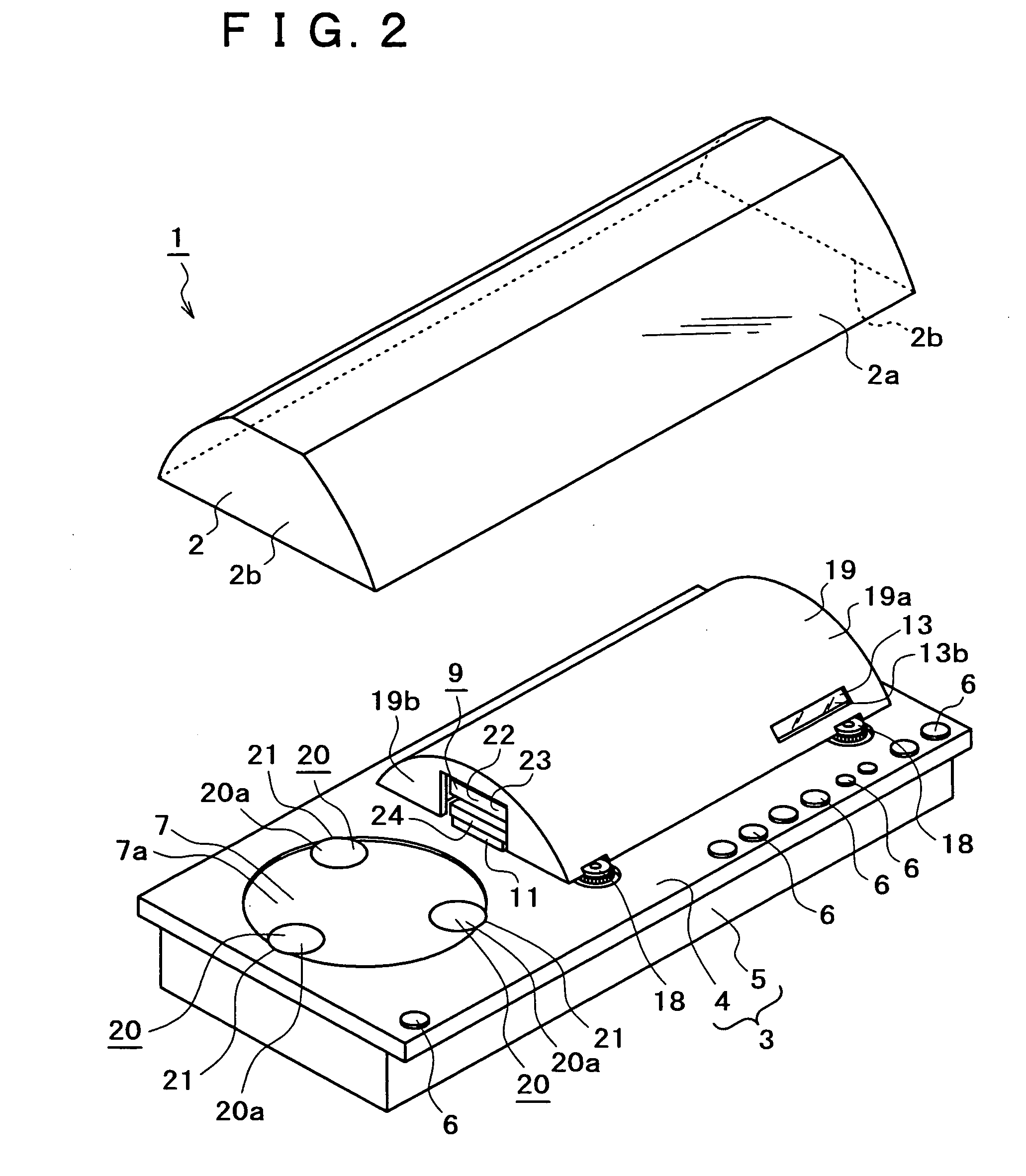
[0078] As shown in FIGS. 1 and 2, a disk drive device 1 according to an embodiment of the present invention, which serves to record an information signal on and reproduce an information signal from a disk-shaped recording medium, comprises a cover 2, a base body 3, and various components and mechanisms mounted on the base body 3.

[0079] The cover 2 is made of a transparent material such as glass, synthetic resin, or the like, and has a substantially wagon-roofed shape that is open downwardly and elongate in one direction. The cover 2 comprises a hood 2a having a substantially arcuate transverse cross section and a pair of end walls 2b attached to the respective opposite longitudinal ends of the hood 2a, the hood 2a and the end walls 2b being integrally joined to each other.

[0080] In the description which follows, the longitudinal direction of the cover 2 is anteroposterior, and directions that are perpendicular to the longitudinal direction of the cover 2 are vertical and lateral. ...


PUM

PropertyMeasurementUnit
timeaaaaaaaaaa
diameteraaaaaaaaaa
Vertical displacementaaaaaaaaaa

Abstract

A chucking pulley clamps and chucks a disk-shaped recording medium in coaction with a disk table, the chucking pulley having a rotary slide knob. The chucking pulley is rotatably supported on a support arm. The support arm has first lifting/lowering pins and second lifting/lowering pins. A holder is fixedly mounted on the support arm for pressing the chucking pulley toward the disk table while being held in contact with a distal end of the rotary slide knob when the disk-shaped recording medium is in rotation. A bias spring is resiliently held against the first lifting/lowering pins. Moving members are arranged to move the chucking pulley toward and away from the disk table. The moving members have retainers for retaining the first lifting/lowering pins in an acting position when the disk-shaped recording medium is chucked. The first lifting/lowering pins retained in the acting position elastically deform the bias spring to bias the support arm and the holder to move toward the disk table.

Description

BACKGROUND OF THE INVENTION [0001] The present invention relates to a disk chucking mechanism and a disk drive device, and more particularly to the art of increasing the positional accuracy of various components to provide a low-profile structure for such a disk chucking mechanism and a disk drive device. [0002] There are known disk drive devices for recording an information signal on and reproducing an information signal from a disk-shaped recording medium such as an optical disk, or a magneto-optical disk. The known disk drive devices include a disk drive device of the type a disk chucking mechanism having a disk table for mounting a disk-shaped recording medium thereon and a chucking pulley for gripping and chucking the disk-shaped recording medium in coaction with the disk table. For details, reference should be made to Japanese Patent Laid-open No. Hei 6-180913 and Japanese Patent Laid-open No. Hei 9-265705, for example. [0003] The disk drive device operates as follows: When a ...

Claims


Application Information

Patent Timeline
Patent Type & Authority Applications(United States)
IPC IPC(8): G11B17/028
CPCG11B17/0288G11B17/0286
Inventor OSADA, YASUO
Owner SONY CORP
Why Eureka
Try Eureka