
Workpiece holding frame

a workpiece and frame technology, applied in the field of workpiece holding frames, can solve the problems of limited movement of the print head, difficult positional alignment between the print pattern and the embroidery pattern, and high labor intensity, and achieve the effect of improving the structur

Inactive Publication Date: 2015-03-05
TOKAI IND SEWING MACH CO LTD
View PDF13 Cites 9 Cited by
  • Summary
  • Abstract
  • Description
  • Claims
  • Application Information

AI Technical Summary

Benefits of technology

[0008]In view of the foregoing prior art problems, it is an object of the present invention to provide a workpiece holding frame with an improved structure which can subject a workpiece to selectively both of printing and embroidery processes without having to change the stretched-taut state of the workpiece on the holding frame.
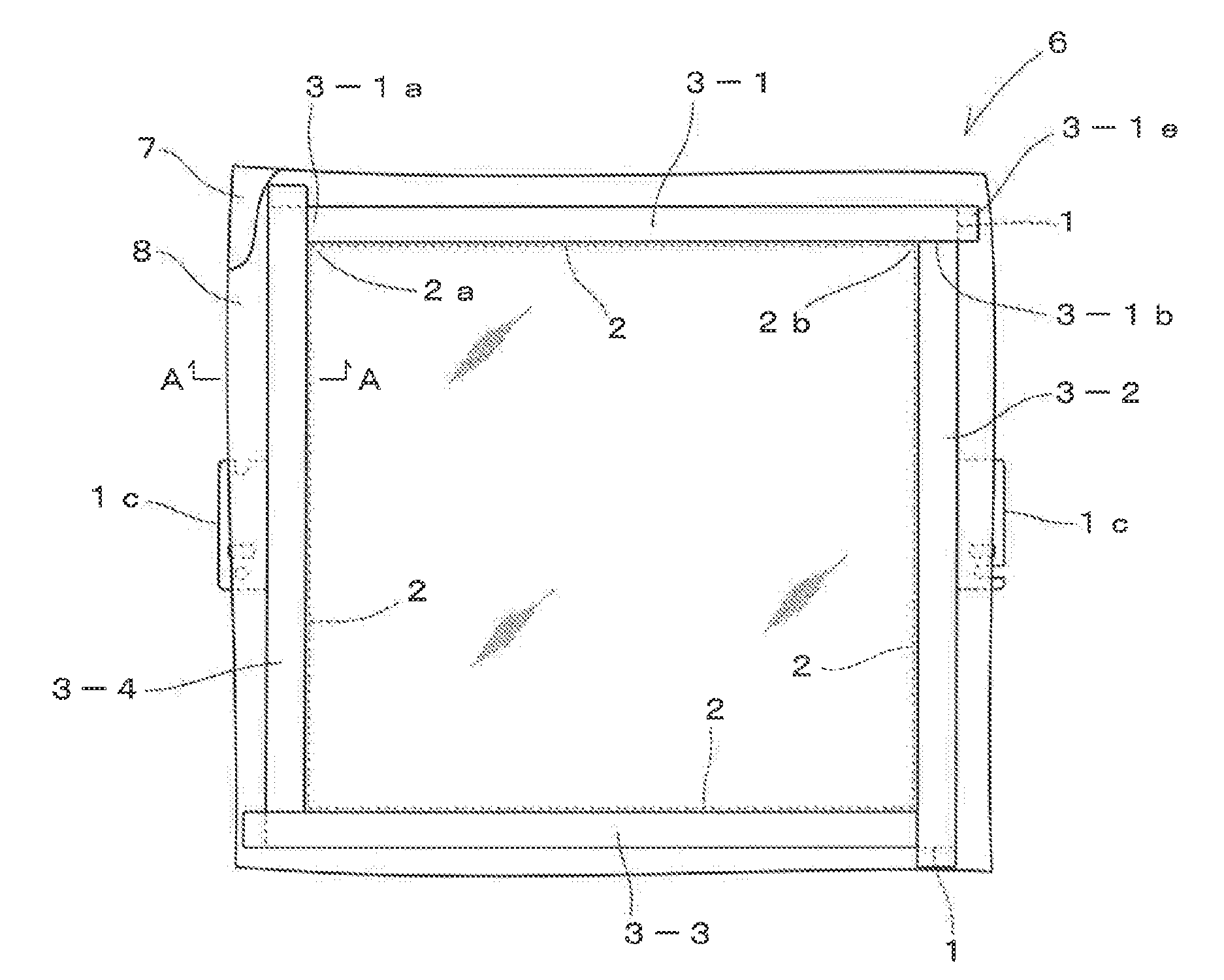
[0009]In order to accomplish the above-mentioned object, the present invention provides an improved workpiece holding frame which holds a workpiece such that the workpiece can be subjected to selectively both of printing and embroidery processes, and which comprises: a holding frame main body having at least one frame side; and at least one holding piece directly attracted by magnetic force towards the frame side of the holding frame main body, wherein the workpiece in the form of a sheet is sandwiched and held between the frame side and the holding piece, causing the workpiece to be in a stretched taut at a lower surface of the holding frame, thereby allowing the workpiece to be subjected to selectively both of printing and embroidery processes without having to change the stretched-taut state.
[0010]According to the present invention, the holding piece that cooperates functionally with the holding frame main body to sandwich a workpiece therebetween is constructed such that it is directly attracted by magnetic force towards the frame side of the holding frame main body. Accordingly, the overall structure of holding frame main body can be made low profile. Therefore, in a state where the holding frame is configured such that a workpiece in the form of a sheet is sandwiched and held between the frame side and the holding piece and the workpiece is stretched taut at the lower surface of the holding frame, the distance between the lower and upper surfaces of the holding frame becomes relatively small, and as a result, if the workpiece is subjected to a printing process without changing the stretched-taut state, an interference of the upper surface height of the holding frame with the printing action can be kept to the minimum as much as possible. Consequently, according to the present invention, a workpiece can be subjected to selectively both of printing and embroidery processes without having to change the stretched-taut state of the workpiece on the holding frame. Further, a deterioration of the quality of embroidery due to a change in the degree of tautness can be eliminated.
[0011]According to an embodiment, a permanent magnet is provided on at least one of the frame side of the holding frame main body and the holding piece, and the magnetic force of the permanent magnet directly penetrates the workpiece sandwiched between the frame side of the holding frame main body and the holding piece such that it acts between the frame side of the holding frame main body and the holding piece. According to such a structure, in the case where the frame side of the holding frame main body and the holding piece are vertically superposed, the thickness in the vertical direction is made relatively low profile and the area of the superposed portion in the lateral direction is made relatively large, so as to ensure sufficient attractive force (that is, a thin plate magnet is used), which is fit for making the overall holding frame structure low profile.
[0012]In the embodiment, the frame side of the holding frame main body may include a flat portion and a rib extending approximately perpendicularly along an inner edge of the flat portion, and the holding piece may be disposed so as to be accommodated in a space defined by the frame sides, which is formed by the flat portion and the rib, and the workpiece sandwiched and held between the frame side and the holding piece is stretched taut on the holding frame main body in a state bent at an end edge of the rib and in contact therewith. With such a simplified construction, the workpiece can be stretched taut, and the simplified overall structure is suitable for making the overall structure of the holding frame low profile.

Problems solved by technology

Thus, with the conventionally-known technique, much time and labor would be required, and positional alignment between a print pattern and an embroidery pattern tends to be difficult.
In such a case, however, movement of the print head is limited because the print head has a great horizontal width and depth, which would result in a considerably reduced printable range.
Thus, when embroidery is to be performed subsequently after removal of the auxiliary frame member, the tautness of the workpiece would slack, producing unwanted slackness or looseness in the workpiece.
As a consequence, quality of an embroidery made in the aforementioned manner would deteriorate.

Method used


Image

  • Workpiece holding frame
  • Workpiece holding frame
  • Workpiece holding frame

Examples


Embodiment Construction

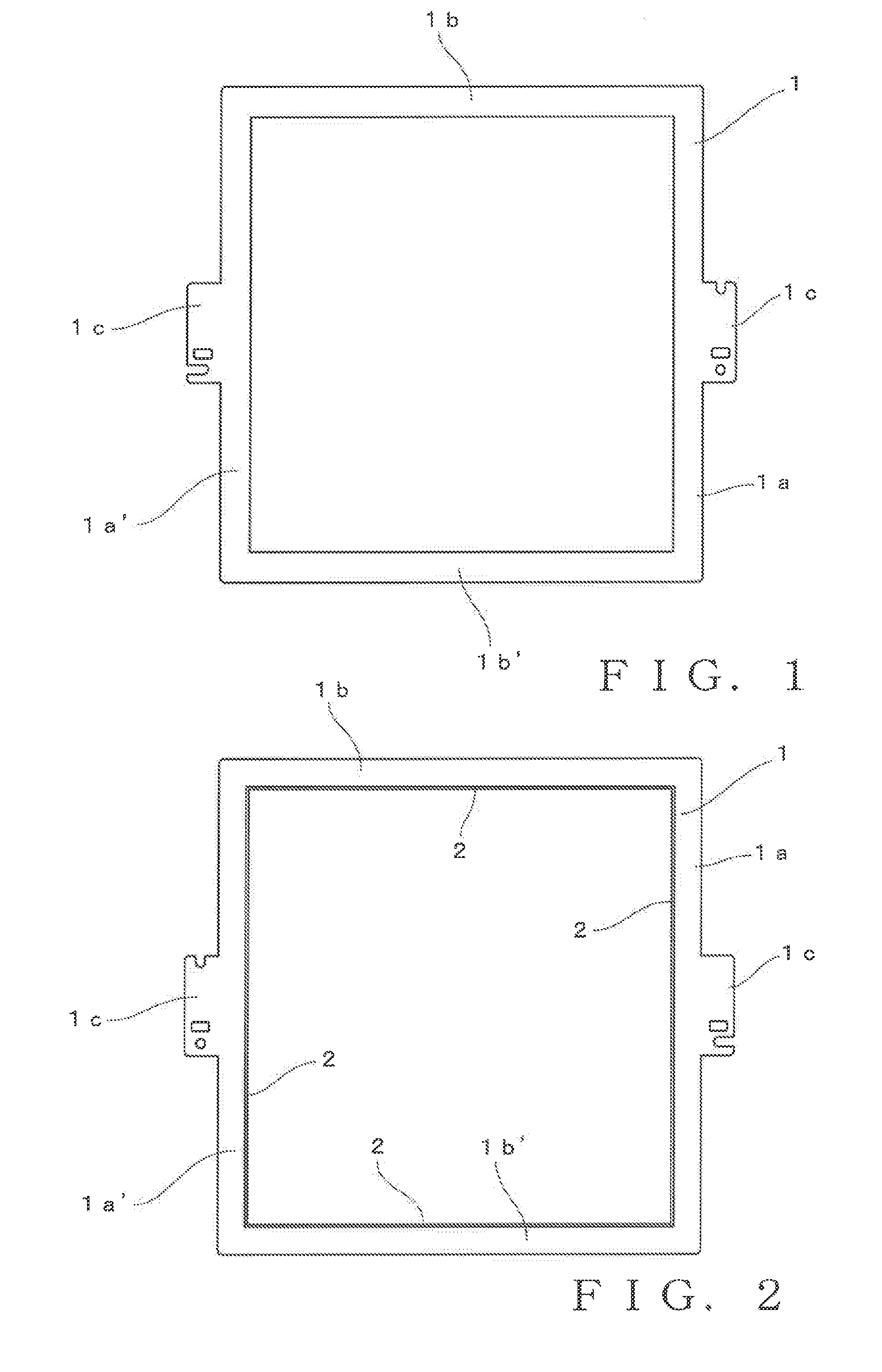
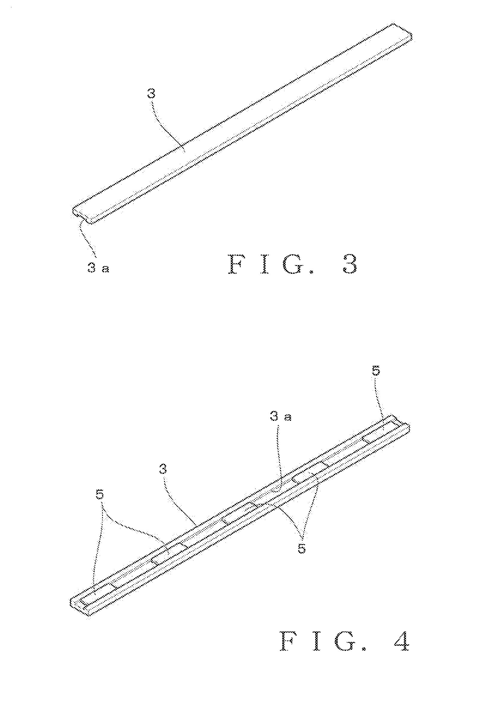
[0025]A holding frame 6 according to the present invention is configured by a combination of a holding frame main body 1 shown in FIGS. 1 and 2 and a holding piece 3 shown in FIGS. 3 and 4. The holding frame main body 1 is configured by a thin plate made of magnetic materials such as a steel plate, and is formed by joining, by means of welding or the like, respective frame sides 1a and 1a′ on right and left sides and respective frame sides 1b and 1b′ on upper and lower sides into a rectangular shape. On opposing inner edges of the respective frame sides 1a, 1a′, 1b and 1b′, a rib 2 bent toward a bottom side at a predetermined width from an end of the inner edge is formed for each frame side, as shown in FIGS. 2 and 5. A height of the rib 2 is, for example, 5 mm or less. Attaching arms 1c are formed respectively on outer sides of the right and left frame sides 1a, 1a′. The attaching arms 1c are provided for attaching the holding frame main body 1 to a frame driving portion (not shown...


PUM


Abstract

A workpiece holding frame includes: a main body having a frame side; and a holding piece directly attracted by magnetic force towards the frame side. A sheet-like workpiece is sandwiched and held between the frame side and the holding piece to make the workpiece stretched taut at a lower surface of the holding frame. The workpiece is subjected to selectively both of printing and embroidery processes without having to change the resulting stretched-taut state. The holding piece has a groove for accommodating therein a permanent magnet. The frame side includes a flat portion and a rib extending perpendicularly along an inner edge thereof, and the holding piece is disposed so as to be accommodated in a space of the frame side which is formed by the flat portion and the rib. The workpiece is bent in contact with an end edge of the rib to be is stretched taut.

Description

BACKGROUND[0001]The present invention relates generally to frames for holding a workpiece, such as a fabric, in a stretched-taut state, and more particularly to a workpiece holding frame detachably attachable to selectively both of a printing apparatus for performing printing on a workpiece and an embroidery sewing machine for performing embroidery on the workpiece while keeping the same workpiece held thereon.[0002]Among a wide variety of embroidery products made today are ones having a combination of printed and embroidered patterns. To make such a product having a combination of printed and embroidered patterns, printing of a desired pattern is performed on a fabric (workpiece) by means of a printing apparatus, and then embroidery of a desired pattern is performed on the fabric by means of an embroidery sewing machine. The printing apparatus, which may comprise for example a printer for use with a personal computer or the like, includes a print head movable in an X direction, and...

Claims


Application Information

Patent Timeline
Patent Type & Authority Applications(United States)
IPC IPC(8): D05C9/04
CPCD05C9/04
Inventor AMAKAWA, YASUTAMINANBA, SHUNZOUOIWA, HIDEKI
Owner TOKAI IND SEWING MACH CO LTD
Learn More