Band clip

a technology of a band clip and a ring is applied in the field of band clips, which can solve the problems of decreasing the space where the wire harness is arranged, increasing the manufacturing cost, increasing the weight etc., and achieves the effects of increasing the stability of the wire harness, reducing the height of the body, and increasing the spa

Inactive Publication Date: 2014-12-02
SUMITOMO WIRING SYST LTD
View PDF42 Cites 12 Cited by
  • Summary
  • Abstract
  • Description
  • Claims
  • Application Information

AI Technical Summary

Benefits of technology

[0010]Accordingly, when the band wrapped around the group of electric wires of the wire harness is fastened by being inserted into the band insertion hole of the vertical plate portion, and the clip attachment hole of the horizontal plate portion and the predetermined locking hole of the band are put into communication with each other, the band can be fixed if the clip, whose shaft portion has been movably fitted into the clip attachment hole, is merely pushed toward the band such that the band locking claw at the shaft portion tip is inserted into and locked to the locking hole in the band. At the same time, the body locking claw at the intermediate position on the shaft portion can be brought into contact with the surface of the body on the opposite side of the band. In this way, the shaft portion does not come out of the locking hole in the band or shift in the shaft front / rear direction due to the shaft portion of the clip being inserted into the locking hole of the band in a fastened state, and due to the shaft front / rear direction wedging of the band locking claw and the body locking claw on the shaft portion, thus maintaining firm binding of the band. Also, since the shaft portion is firmly fixed due to being inserted into and locked to the locking hole in the band, the wing portion on the lower end side of the shaft portion can also be reliably locked to the vehicle body in a stable manner. Accordingly, since there is no need to provide a relatively high upper wall and tall insertion hole internally provided with a protruding tongue for lock binding as in conventional technology, the height of the body can be kept low, there is an increase in the amount of space where the wire harness is arranged, and it is possible to raise the stability of the wire harness when it is fixed to the vehicle body. Weight and manufacturing cost can also be suppressed since there is no need for the upper wall and side walls that are required in the case of a box-shaped body.
[0018]Accordingly, when the band wrapped around the group of electric wires of the wire harness is fastened by being inserted into the band insertion hole of the vertical plate portion, and the clip attachment hole of the horizontal plate portion and the predetermined locking hole of the band are put into communication with each other, the band can be fixed if the clip, whose shaft portion has been movably fitted into the clip attachment hole, is merely pushed toward the band such that the band locking claws at the shaft portion tip are inserted into and locked to the locking hole in the band. At the same time, the body locking claws at intermediate positions on the shaft portion can be brought into contact with the surface of the body on the opposite side of the band. In other words, the shaft portion does not come out of the locking hole in the band or shift in the front / rear direction due to the shaft portion of the clip being inserted into the locking hole of the band in a fastened state, and due to the shaft front / rear direction wedging of the band locking claws and the body locking claws on the shaft portion, thus maintaining firm binding of the band. Accordingly, since there is no need to provide a relatively high upper wall and tall insertion hole internally provided with a protruding tongue for lock binding as in conventional technology, the height of the body can be kept low, there is an increase in the amount of space where the wire harness is arranged, and it is possible to raise the stability of the wire harness when it is fixed to the vehicle body. Weight and manufacturing cost can also be suppressed since there is no need for the upper wall and side walls that are required in the case of a box-shaped body.

Problems solved by technology

As the height H of the body 2 rises, the amount of space where the wire harness is arranged decreases, and there are cases where stability deteriorates due to a rise in the height of the barycentric position of the wire harness fixed to the vehicle body.
In addition to the lower wall 2b out from which the clip 6 protrudes, the body 2 also needs to be provided with the upper wall 2a and side walls 2c for forming the insertion hole 3, and these walls 2a and 2c create the problem of an increase in weight and an increase in manufacturing cost.

Method used


Image

  • Band clip
  • Band clip
  • Band clip

Examples


Embodiment Construction

[0025]Hereinafter, an embodiment of a band clip of the present invention will be described with reference to the drawings.

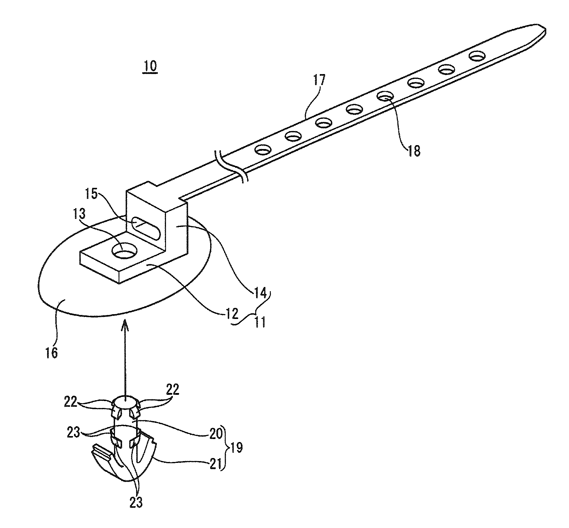
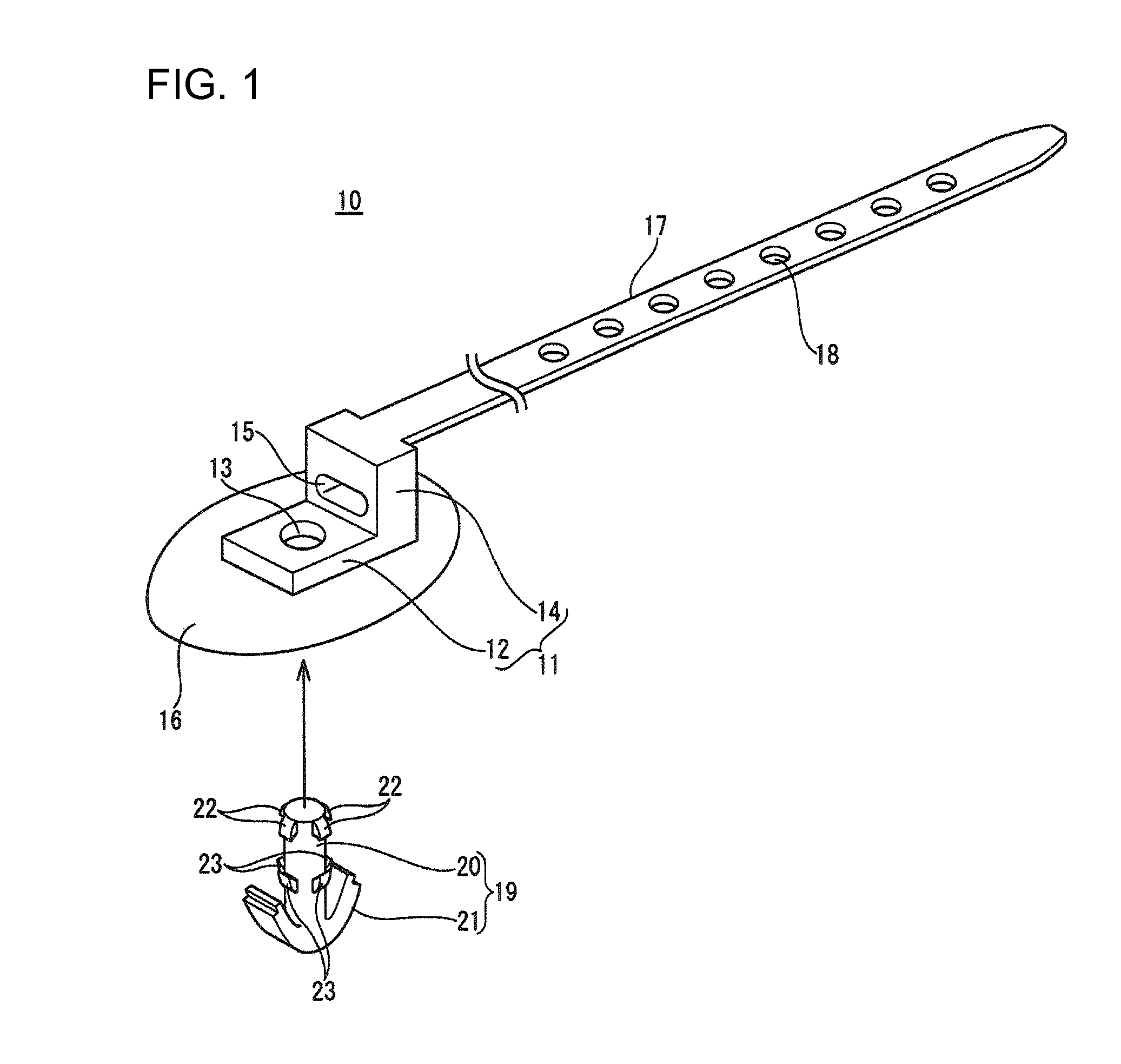
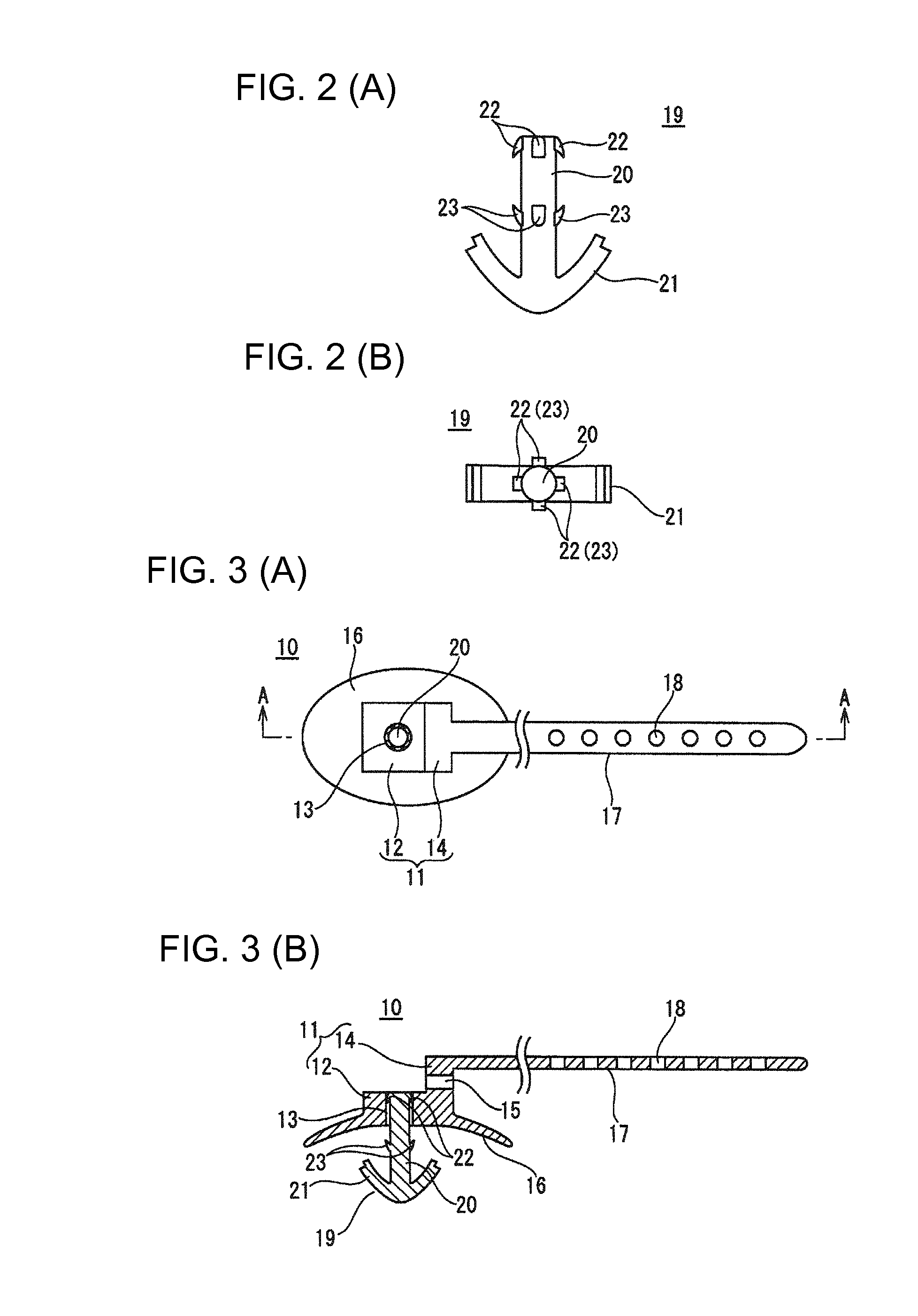
[0026]FIGS. 1 to 5 show an embodiment of the present invention. As shown in FIG. 5, a band clip 10 of the present embodiment is for binding and fixing a band 17, which is wrapped around a group of electric wires D of a wire harness that is to be arranged in an automobile, at a position in a body 11, and for fixing the group of electric wires D of the wire harness to a vehicle body due to a clip 19, which protrudes out from a lower face of the body 11, being inserted into and locked to a panel hole 31 in a vehicle body panel 30. The band clip 10 is constituted by a resin-molded piece, and is configured from the body 11, the band 17, which is molded integrally with the body 11 so as to extend out therefrom, and the clip 19 for vehicle body locking, which is moveably attached to the body 11 and protrudes out from the lower face of the body 11.

[0027]The body 11 is L-...


PUM


Abstract

A band clip includes a body, a band integral with the body, and a clip that is attached to the body. The body has a vertical plate with a band insertion hole and a horizontal plate with a clip attachment hole. The band extends from the vertical plate. Locking holes penetrate the band at intervals. The clip includes a shaft that is fit into the clip attachment hole of the body, a wing on one end of the shaft, a band locking claw at another end of the shaft, and a body locking claw on an intermediate portion of the shaft. The band is wrapped around a group of wires and inserted into the band insertion hole. The band locking claw of the clip is inserted into and locked to a band locking hole, and the body locking claw contacts the surface of the body.

Description

BACKGROUND[0001]1. Field of the Invention[0002]The present invention relates to a band clip, and specifically reduces the height of a body portion that binds and fixes a band that is wrapped around a group of electric wires of a wire harness.[0003]2. Description of the Related Art[0004]Various shapes of resin-molded band clips have conventionally been used to bind groups of electric wires of wire harnesses that are arranged in automobiles and the like, and to fix the wire harnesses to a vehicle body. A conventional band clip 1 includes, as shown in FIGS. 6(A) to 6(C) for example, a box-shaped body 2 for the insertion and locking of a band 5 that is wrapped around a group of electric wires D of a wire harness, the band 5 that extends out from the body 2, and a clip 6 that protrudes out from the outer face of the body 2 and is inserted into and locked to a panel hole in a vehicle body panel. An insertion hole 3 for insertion of the band 5 is provided in the body 2, a tongue (elastic p...

Claims


Application Information

Patent Timeline
Patent Type & Authority Patents(United States)
IPC IPC(8): F16L3/08F16B21/08H02G3/32F16L3/137
CPCH02G3/32F16L3/137F16B21/086Y10T24/1498B60R16/0215F16B2/08F16B19/004H02G3/30
Inventor TANAKA, HIROAKI
Owner SUMITOMO WIRING SYST LTD
Why Eureka
Try Eureka