Method and system for supplying hydrogen for use in fuel cells

a fuel cell and hydrogen technology, applied in the direction of liquid gas reaction process, hydrogen separation using solid contact, chemical/physical/physicochemical stationary reactor, etc., can solve the problems of reducing the efficiency of hydrogen recovery, products produced, in addition to hydrogen, not being efficiently utilized in the system, etc., to achieve the effect of increasing the concentration of water vapor, reducing the concentration of hydrogen, and increasing the concentration of hydrogen

Inactive Publication Date: 2002-02-19
MOBIL OIL CORP
View PDF9 Cites 314 Cited by
  • Summary
  • Abstract
  • Description
  • Claims
  • Application Information

AI Technical Summary

Benefits of technology

By recycling a portion of the retentate stream to the reforming reactor higher yields of hydrogen per mole of hydrocarbon reacted can be achieved. For example, thermodynamic calculations suggest that recycling a portion of the retentate stream 42 shifts the equilibrium of Equations (I, II, and III) to produce more hydrogen. This results because the retentate stream 42 contains primarily water vapor and is partially depleted of hydrogen, thereby reducing the concentration of hydrogen and increasing the concentration of water vapor in the reforming reaction zone. This shift in hydrogen and water vapor concentrations in the reforming reaction zone drives the reaction equilibriums to produce more hydrogen, and less methane and carbon monoxide. Although the retentate stream 42 als...

Problems solved by technology

However, increasing the amount of water drives the reactions to produce hydrogen.
For example, one problem has been finding efficient ways to supply heat for starting-up and maintaining the reforming reaction which is endothermic.
However, the systems of Isomura and Takahashi are sub-optimal i...

Method used


Image

  • Method and system for supplying hydrogen for use in fuel cells

Examples


example 1

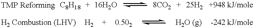
A heat balance for the autothermal reforming of isooctane, also known as 2,2,4-trimethylpentane (TMP), was performed to estimate the potential for hydrogen production from gasoline for use in automotive fuel cell applications. TMP is a desirable, 100 octane rated, component found in commercial gasoline containing alkylates. A simple heat balanced model was constructed using a commercially obtained process simulation package, PRO / II steady state flow-sheeting and process optimization software by Simulation Sciences, Inc. located in Brea, Calif. In the absence of thermodynamic equilibrium constraints, the endothermic steam reforming of TMP can be written as follows: ##STR1##

Hydrogen combustion is extremely exothermic. Using the simulation software, the net heat balance for the autothermal reforming of TMP was calculated using enough moles of oxygen, sourced from air, for combusting that portion of the hydrogen to just meet the thermal duty requirements of the autothermal reforming rea...

example 2

Thermodynamic equilibria of the reforming reaction and the more practical aspects of heat recovery make the achievement of the hydrogen production efficiency noted in Example 1 extremely difficult. With respect to thermodynamic equilibria, hydrogen production during reforming is favored by increasing reaction temperatures and decreasing reaction pressures. For example, TMP reforming reaction simulations were run at various reaction temperatures and reaction pressures using the PRO / II steady state flow-sheeting and process optimization software (previously used in Example 1). The simulations assumed that thermodynamic equilibrium conditions were reached. FIGS. 4A and 4B show the results of the simulations at a steam to feed carbon ratio of 3:1. FIGS. 4A and 4B show the reformate stream composition (measured in mole fraction) exiting a reforming reactor at equilibrium versus temperature (in .degree. C.). In FIG. 4A, the reforming reaction pressure was set at 100 kPa and in FIG. 4B, th...

example 3

A computer simulation of a reforming reaction was developed and run to demonstrate the benefits of recycling a portion of the retentate stream to the reforming reactor. The computer software package used to develop the computer simulation was the PRO / II steady state flow-sheeting and process optimization software previously described.

The simulation that was developed assumed that the reforming reactor was operated at equilibrium so that the Gibbs free energy of the system was zero. The simulation also assumed a reactor configuration similar to FIG. 1 where the reformate stream 32 exiting the reforming reactor 12 is directed to a hydrogen separating membrane 14 having a retentate side 36 and permeate side 38. The retentate stream 42 on the retentate side 36 of the hydrogen separating membrane 14 was assumed to be directed through a splitter 44 to recycle varying amounts of retentate stream (i.e., retentate recycle stream 46) to the reforming reactor. The simulation did not include a ...


PUM

PropertyMeasurementUnit
Pressureaaaaaaaaaa
Angleaaaaaaaaaa
Fractionaaaaaaaaaa

Abstract

The present invention provides a method and system for efficiently producing hydrogen that can be supplied to a fuel cell. The method and system of the present invention produces hydrogen in a reforming reactor using a hydrocarbon stream and water vapor stream as reactants. The hydrogen produced is purified in a hydrogen separating membrane to form a retentate stream and purified hydrogen stream. The purified hydrogen can then be fed to a fuel cell where electrical energy is produced and a fuel cell exhaust stream containing water vapor and oxygen depleted air is emitted. In one embodiment of the present invention, a means and method is provided for recycling a portion of the retentate stream to the reforming reactor for increased hydrogen yields. In another embodiment, a combustor is provided for combusting a second portion of the retentate stream to provide heat to the reforming reaction or other reactants. In a preferred embodiment, the combustion is carried out in the presence of at least a portion of the oxygen depleted air stream from the fuel cell. Thus, the system and method of the present invention advantageously uses products generated from the system to enhance the overall efficiency of the system.

Description

The present invention relates to a method and system of supplying hydrogen for use in a fuel cell. The system and method produces hydrogen by a reforming reaction of a hydrocarbon stream, and is particularly useful for supplying hydrogen to vehicles and stationary structures that use fuel cells.Recently there have been efforts to develop systems for supplying hydrogen to fuel cells that are used in such applications as vehicles, such as cars and buses, or stationary structures such as industrial plants. One such type of system that has been proposed obtains hydrogen from a reforming reaction of hydrocarbons or oxygen containing hydrocarbons. The hydrogen produced is purified in a hydrogen membrane separator before being used in the fuel cell.The major reactions that occur in reforming can be represented by the following equations:C.sub.n H.sub.2(n+1) +nH.sub.2 O.fwdarw..rarw.nCO+(2n+1)H.sub.2 (Endothermic) Equation (I)C.sub.n H.sub.2(n+1) +2nH.sub.2 O.fwdarw..rarw.nCO.sub.2 +(3n+1)H...

Claims


Application Information

Patent Timeline
IPC IPC(8): B01J19/24B01J8/02B01B1/00C01B3/50C01B3/38C01B3/00H01M8/06H01M8/04C01B3/56H01M8/00H01M8/10
CPCB01B1/005B01J8/0278B01J8/0285B01J19/2485C01B3/384C01B3/501H01M8/0612B01J8/0207Y02B90/12B01J2208/00132B01J2208/00194B01J2208/00309B01J2208/00398B01J2208/00415B01J2208/00539B01J2208/00716B01J2219/00006B01J2219/00011B01J2219/00081B01J2219/00117B01J2219/00135C01B2203/0233C01B2203/0405C01B2203/047C01B2203/0475C01B2203/048C01B2203/0495C01B2203/066C01B2203/0811C01B2203/0822C01B2203/0827C01B2203/085C01B2203/0866C01B2203/0883C01B2203/1017C01B2203/1023C01B2203/1035C01B2203/1041C01B2203/1052C01B2203/1064C01B2203/107C01B2203/1205C01B2203/1247C01B2203/1258C01B2203/1288C01B2203/148C01B2203/1604H01M8/04022H01M8/04089H01M8/04156H01M8/04223H01M8/0625H01M8/0662H01M2250/20H01M2250/402Y02T90/32Y02E60/50Y02B90/10Y02T90/40Y02P20/10H01M8/04302
Inventor LAPIERRE, RENE B.PARTRIDGE, RANDALL D.
Owner MOBIL OIL CORP
Why Eureka
Try Eureka