Eureka AIR delivers breakthrough ideas for toughest innovation challenges, trusted by R&D personnel around the world.

Fuel cell system and control method thereof

A fuel cell system and controller technology, which is applied in the direction of fuel cells, fuel cell additives, and reactant parameter control. It can solve the problems of high water content in the stack gas, inability to effectively remove water, and affect performance. Flexible control strategy, improved fuel utilization, and optimized air circuit effects

Pending Publication Date: 2021-01-15
金华氢途科技有限公司
View PDF0 Cites 13 Cited by
  • Summary
  • Abstract
  • Description
  • Claims
  • Application Information

AI Technical Summary

Problems solved by technology

[0003] However, in the general fuel cell system, there will be the following disadvantages: 1. The performance of the long-distance cross-altitude driving vehicle will be reduced due to environmental changes; Low; 3. There is no adjustment function for the degree of humidification of the cathode gas of the vehicle, which may cause excessive water content in the gas entering the stack, causing flooding of the stack, affecting performance and damaging the stack; 4. After the fuel cell system is shut down, Air can enter the electric stack from the air compressor, resulting in high oxygen content in the electric stack; 5. During the start-up and shutdown of the fuel cell system, the hydrogen purging process, the air compressor is not running, the throttle valve is not open, and the hydrogen concentration in the tail gas is relatively high. 6. When starting at low temperature, the water in the stack is discharged through high-pressure air, and the gas at the inlet and outlet of the stack passes through the humidifier for humidity and heat exchange, and the discharged water vapor will enter again after being exchanged by the humidifier. stack, unable to effectively remove water
[0004] Because different stacks have different structural characteristics, operating conditions and other system integration differences, the traditional fuel cell system design process is mainly designed and developed around the current working conditions and structures of the stack, and the adaptability to other stacks is low, so It is necessary to design a system design scheme that can solve the above technical problems and be compatible with most stacks with different needs, so that the system products are more competitive and adaptable, and have a degree of freedom that can be self-regulated

Method used


Image

  • Fuel cell system and control method thereof
  • Fuel cell system and control method thereof
  • Fuel cell system and control method thereof

Examples


Embodiment Construction

[0042] It should be pointed out that the following detailed description is exemplary and intended to provide further explanation to the present application. Unless defined otherwise, all technical and scientific terms used herein have the same meaning as commonly understood by one of ordinary skill in the art to which this application belongs.

[0043] It should be noted that the terminology used here is only for describing specific implementations, and is not intended to limit the exemplary implementations according to the present application. As used herein, unless the context clearly dictates otherwise, the singular is intended to include the plural, and it should also be understood that when the terms "comprising" and / or "comprising" are used in this specification, they mean There are features, steps, operations, means, components and / or combinations thereof.

[0044] Furthermore, in describing the present invention, it is to be understood that the terms "center", "longit...


PUM


Abstract

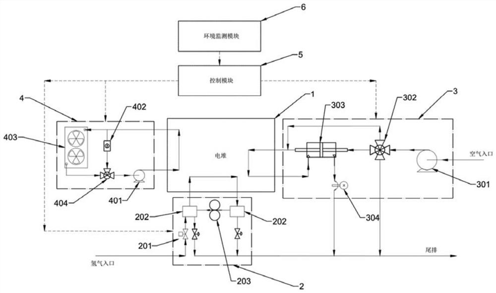
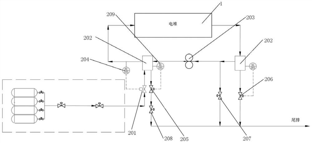
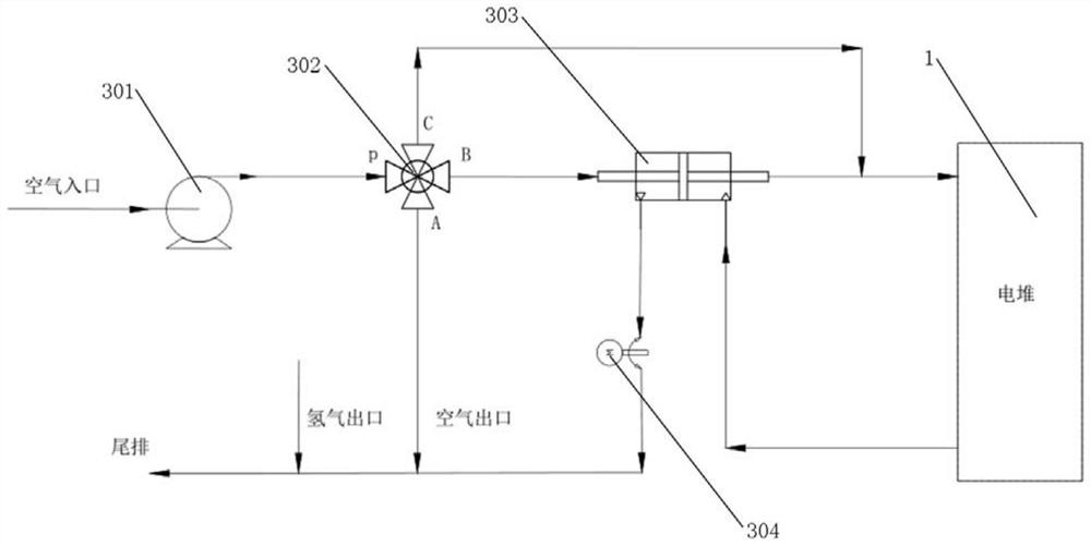
The invention relates to a fuel cell system and a control method thereof. The system comprises a galvanic pile, a hydrogen loop, an air loop, a cooling loop, a control module and an environment monitoring module, the hydrogen loop, the air loop and the cooling loop are all connected with the galvanic pile, and the control module receives information of each loop and the environment monitoring module, and regulates and controls each loop through calculation; the air loop comprises an air inlet pipeline, an air compressor, a cathode flow control module, a humidifier, a throttle valve and an exhaust pipeline, the air inlet pipeline, the air compressor, the humidifier and the inlet end of the galvanic pile are sequentially connected through pipelines, and the outlet end of the galvanic pile issequentially communicated with the humidifier, the throttle valve and the exhaust pipeline. And the cooling loop comprises a second pressure controller, a heater, a multi-module heat dissipation module and a flow control module. The defects in a common fuel cell are overcome, and the adaptive capacity of the system for different environments is improved.

Description

technical field [0001] The invention relates to the field of fuel cell engines, in particular to a fuel cell system and a method thereof. Background technique [0002] The fuel cell system is a device that uses the fuel cell stack as the core, uses hydrogen as the fuel, and air as the oxidant for gas supply, exhaust, and power generation. The system can be divided into three main circuits: hydrogen circuit, air circuit and cooling circuit. The hydrogen circuit is the fuel input channel, and high-purity hydrogen is introduced from an external gas source (such as a hydrogen storage bottle or a hydrogen production device, etc.), and the hydrogen channel performs functions such as fuel pressure and flow control, reaction gas recycling, and water vapor separation; the air The loop is responsible for transporting, pressurizing, and humidifying the oxidant (i.e., air) required for the fuel cell reaction; the main function of the cooling loop is heat management and transportation, ...

Claims


Application Information

Patent Timeline
Patent Type & Authority Applications(China)
IPC IPC(8): H01M8/04119H01M8/04029H01M8/04082H01M8/04089H01M8/04701H01M8/04746
CPCH01M8/04029H01M8/04089H01M8/04164H01M8/04201H01M8/04723H01M8/04761H01M8/04768Y02E60/50
Inventor 周鸿波郭志阳陆建山刘志洋刘小娅
Owner 金华氢途科技有限公司
Why Eureka
Eureka Blog
Learn More