Waste storage device

a technology for storage devices and receptacles, which is applied in the field of receptacles with receptacles, can solve the problems of inconvenient location of receptacles in a remote location, inconvenient use, and general unsatisfactory results

Inactive Publication Date: 2005-03-03
CHOMIK RICHARD S +5
View PDF81 Cites 110 Cited by
  • Summary
  • Abstract
  • Description
  • Claims
  • Application Information

AI Technical Summary

Benefits of technology

[0022] According to another embodiment of the invention there is provided a waste container with an automated twisting feature, a tubing cassette rotationally mounted to a flange support; and a retention means for preventing rotation of a waste packet contained in a portion of the tubing when the tubing cassette is rotated, such that a twist is efficiently created in the tubing. The flange may be configured to allow rotation of the tubing cassette. The cassette may be rotated by electrical power as for example by a motorized rotating grip to create a closure twisting action of the flexible tubing when sequestering a waste packet. A motorized apparatus of this embodiment of the invention may optionally provide a plunging device for downwardly pushing the flexible tubing a predetermined distance, thereby providing sufficient space for depositing a waste packet.
[0031] Embodiments may optionally comprise a film grip ring for gripping or holding the flexible tubing in place in order to prevent the inadvertent release of the stored tubing from the rotating cassette during the twisting operation. This advantageous aspect assists in creating a measurably effective tight twist lock of the sequestered waste packet in the tubing segment.
[0037] In one embodiment, the lid is opened by foot operated or activated mechanism which acts upon the lid at the latch mechanism which causes the lid to be in the open position. A waste load is deposited into the open center of the cassette. Upon release of foot-operated mechanism, the lid is caused to close so that the motorized actuator mechanism acts by a cog gearing system causing it to rotate a cassette holding a tubing bag receptacle. The rotation accomplishes two activities for sequestering a diaper or similar waste load and dropping or moving the same downwardly into the tubing bag. At the closed lid position, the actuator initiates the rotation placing a force on the tubing cassette by a cassette twister exerting pressure on the beveled ring surface of the cassette. The rotational movement is measured to continue until sufficiently tight twisting has been effected on the tubing bag so as to close the top opening and thereby retain the waste load. At the moment when the twisting or tightening by cassette rotation is complete for sufficient closure of the tubing tubular bag, a vertically dispensed gearing mechanism, for example, may be turned on and cause a downward movement of the thrust plate. This downward thrust may be mediated through a scissor link assembly which stretches out to extend along the axis of the cassette opening, moving the sequestered waste load downward. Simultaneous to the motorized rotational force applied on the cassette rim, a film grip ring may be activated to contact and clamp down on to the flexible tubing emanating and hanging over the top edge of the inner core tube of the tubing cassette. This contact prevents release of tubing from the storage compartment of the cassette during the rotational twisting operation.
[0041] In a further embodiment, the waste disposal device comprises a container defining a waste chamber for receiving encapsulated waste packages; a lid coupled to the container and movable between an open position in which chamber is accessible and a closed position in which the chamber is covered; a cartridge arranged in the container and containing a length of flexible tubing arranged to receive waste packages; a retention mechanism for holding a waste package received in the tubing, the retention mechanism being fixed to the container; a rotation mechanism arranged to rotate the cartridge relative to the retention mechanism in order to twist the tubing and encapsulate a waste package when held by the retention mechanism; and a toothed member attached to the lid, the cartridge comprising a gear rim, the rotation mechanism engaging with the toothed member and the gear rim during movement of the lid and comprising at least one gear arranged in the container for enabling the conversion of movement of the lid to rotational movement of the gear rim.

Problems solved by technology

However, most lids are not designed to be perfectly air-tight in respect of their receptacles, or after repeated use become less-than air tight, permitting malodor to emanate from the receptacles even when they are closed.
Even with the most air-tight containers, upon opening the container, noxious odors escape into the ambient environment giving an extremely unpleasant sensation to the person attempting to add more trash to the receptacle.
Location of the receptacles in a remote location is inconvenient and generally unsatisfactory.
A particularly difficult trash to retain for ultimate disposal is odoriferous trash.
The cumulative odor of odoriferous trash being stored within the container frequently reaches such an offensive level that the trash must be disposed of before the container is full.
The latter problem typically results in excessive emptying operations.
A further problem associated with such containers is that the containers themselves over time tend to retain the malodor even when no diapers are present in the containers.
Furthermore, as most disposal receptacles are not child-proof, toddlers playing around such containers may inadvertently open a container to allow odors to escape, or the child may reach in to touch the undesirable trash.
The problem with such receptacles is that the masking smell itself can often become irritating to the consumer, as well as the fact that most scented diaper pails loose their masking effect after a period of time.
There are a number of disadvantages with this device including the need for latches to prevent the wheels extending from the heating elements from inadvertently returning up the central track portions (as opposed to following the outer track portions as they should.
A further disadvantage is that the heating element must be at least the width of the tube in order to seal the tube all the way across thereby preventing, for example, the escape of odors from the waste.
A disadvantage of the system is that the twists between packages may become unraveled, thereby allowing groups of diapers to collect within the tubing, which makes emptying the container more difficult.
Further, the twists may not create a continuous, complete seal and, therefore, may allow odor to escape from a package.
From the above it can be understood by those having ordinary skill in the art that there are a number of disadvantages associated with prior art waste disposal devices using flexible tubing and tubular sealing material to form packets for disposal of waste materials.

Method used


Image

  • Waste storage device
  • Waste storage device
  • Waste storage device

Examples


Embodiment Construction

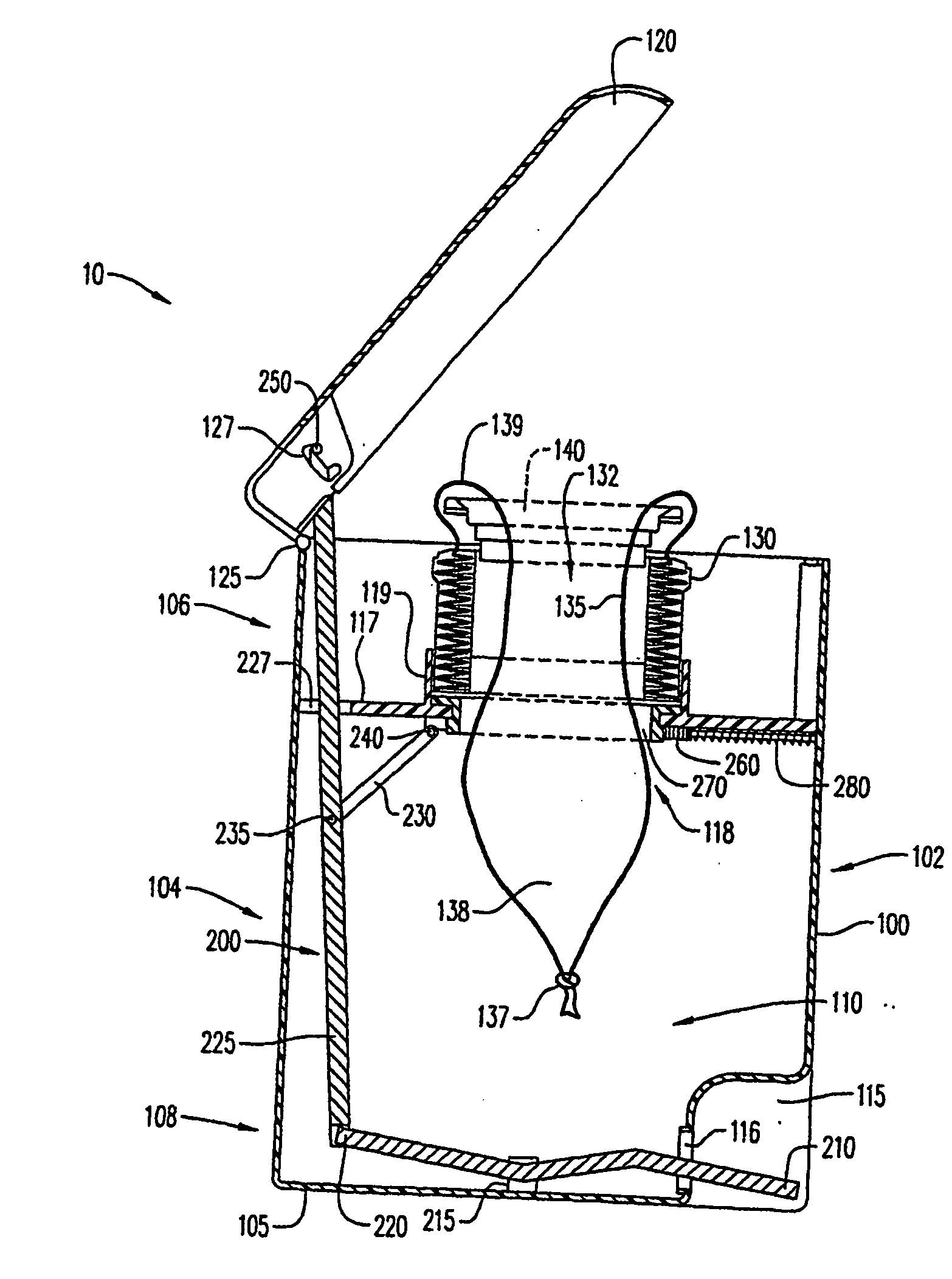
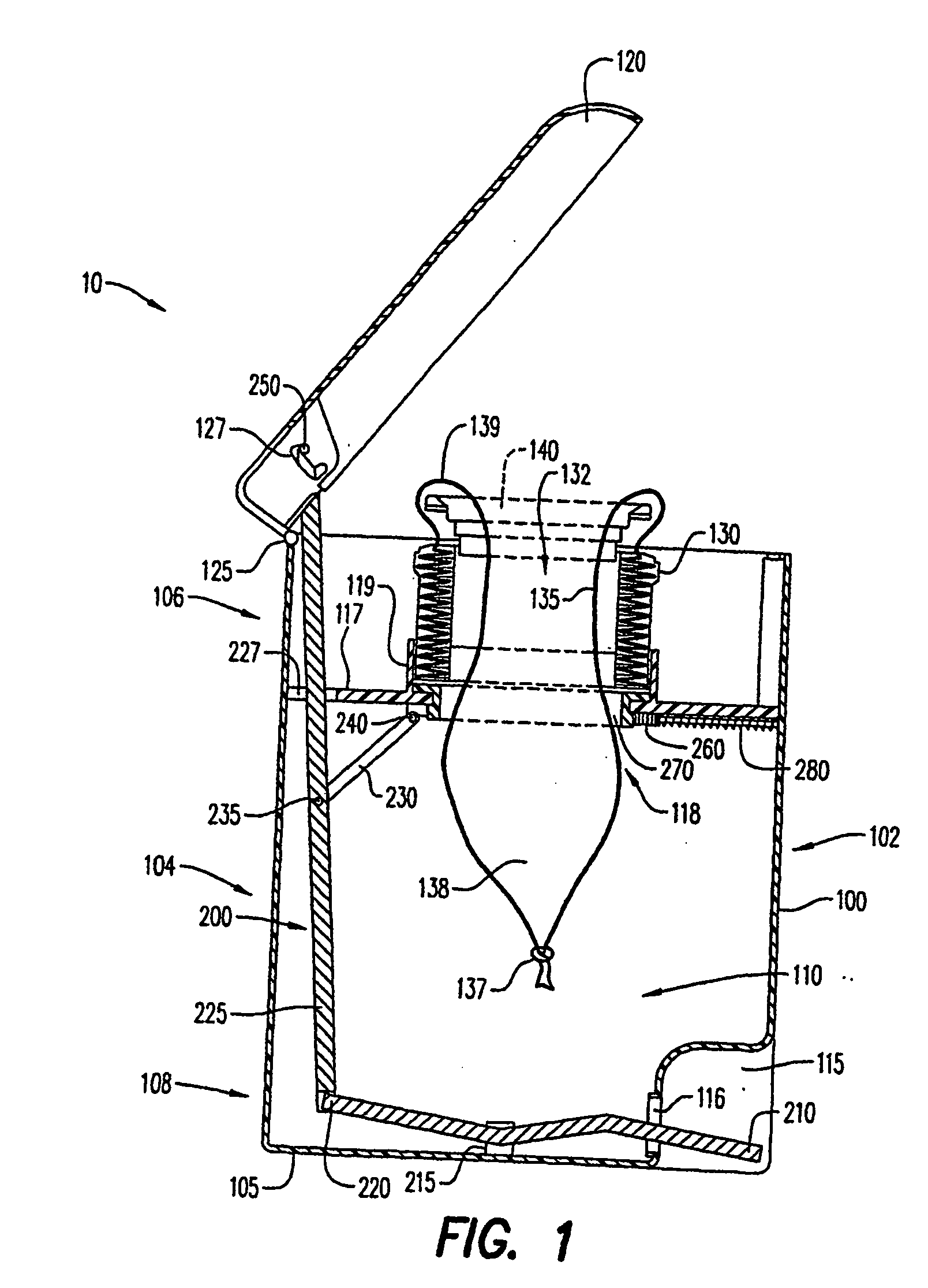
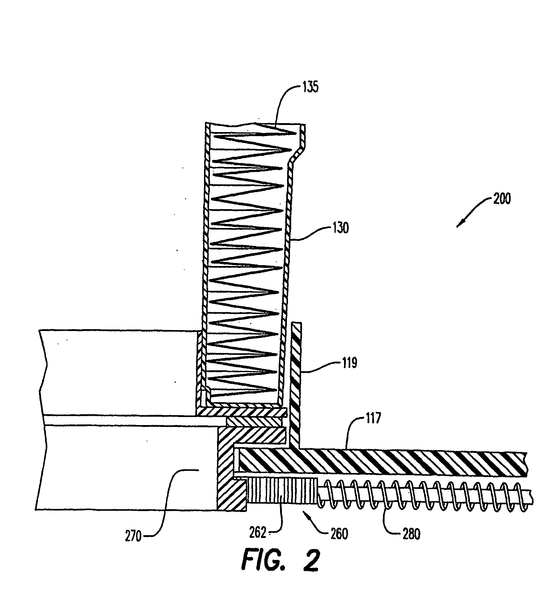
[0091] Referring to FIG. 1, there is shown an embodiment of a waste storage device having the sealing mechanism of the present invention, generally represented by reference numeral 10.

[0092] Waste storage device 10 has a body 100, a lid 120, a storage film cassette 130, a film ring 140 and a sealing mechanism 200. Body 100 has a base 105, an inner volume 110, front and rear portions 102, 104, and upper and lower portions 106, 108. Body 100 is substantially cylindrical in shape to maximize inner volume 110. However, alternative shapes for body 100 can also be used including rectangular or cubical. Lower portion 108 of body 100 has an indentation or pedal housing 115 that will be described later in greater detail. Preferably, pedal housing 115 is positioned along front portion 102.

[0093] Lid 120 is substantially cylindrical in shape and has a diameter substantially the same size as the diameter of body 100 to provide a sealing engagement of the lid with the body along upper portion ...


PUM

PropertyMeasurementUnit
lengthaaaaaaaaaa
flexibleaaaaaaaaaa
timeaaaaaaaaaa

Abstract

The present invention discloses an automated sealing waste disposal apparatus using tubular material.

Description

CROSS-REFERENCE TO RELATED APPLICATIONS [0001] This application is a continuation-in-part application of U.S. Patent Application Serial No. to be assigned, which claims benefit of priority from U.S. Provisional Patent Application Ser. No. 60 / 282,808, filed on 10 Apr. 2001. This application further claims benefit of priority from U.S. Provisional Patent Application Ser. No. 60 / 499,443, filed on 02 Sep. 2003.BACKGROUND OF THE INVENTION [0002] 1. Field of the Invention [0003] The present invention relates to a waste storage device or container. More particularly, the present invention relates to a waste storage device having an automated mechanism for twisting a tubular sealing material about waste, deposited in such tubular sealing material. [0004] 2. Description of the Related Art [0005] Waste receptacles are generally fitted with a lid designed to contain odors when the lid is closed. However, most lids are not designed to be perfectly air-tight in respect of their receptacles, or a...

Claims


Application Information

Patent Timeline
Patent Type & Authority Applications(United States)
IPC IPC(8): B65B7/12B65B67/12B65D85/00B65F1/06B65F1/10B65F1/14B65F1/16
CPCB29C65/38B29C66/1122B65F2240/132B65F2210/1675B65F2210/167B29C66/43B29L2031/7128B65B7/12B65B9/15B65B67/1277B65B2067/1283B65F1/062B65F1/1405B65F1/1426B65F1/1607B65F1/163B65F2210/124B29C65/00B29C66/4312B29C66/83241
Inventor CHOMIK, RICHARD S.YOHO, MARKLESLIE, STUARTKIM, TAEKPETRIE, AIDANSEJNOWSKI, JOE
Owner CHOMIK RICHARD S
Why Eureka
Try Eureka