Solar concentrator for heat and electricity

a concentrator and solar energy technology, applied in the field of solar concentrators, can solve the problems of not reaching the potential use potential of solar energy, limiting the diversity of capture devices, and limiting the range of capture devices, so as to increase the amount of electricity obtained from a given area of incident radiation

Inactive Publication Date: 2000-06-27
JOHNSON COLIN FRANCIS
View PDF8 Cites 311 Cited by
  • Summary
  • Abstract
  • Description
  • Claims
  • Application Information

AI Technical Summary

Benefits of technology

In a subsidiary aspect, the invention further comprises means to concentrate solar radiation onto the energy absorbing surface, thereby providing an increased output from a given area of energy absorbing surface yet avoiding excessive heating of the energy absorbing surface.
In a fourth broad aspect the invention provides a more efficient solar cell installation in that removal of superfluous heat from the cells causes them to remain cooler and thereby operate more efficiently.
In a sixth aspect the amount of electricity obtained from a given area of incident radiation may be increased by raising the surface area of the photovoltaic cells as by arranging them over protrusions on a surface.

Problems solved by technology

Solar energy has not, as yet, approached its potential for use because of the costs associated with capturing it in a widely useful form.
While a type of solar panels can warm water and some architectural constructions capture the sun's heat to warm a space, these capture devices are rather limited in their diversity.
Another type of solar panel is adapted to convert light into electricity, but the capital cost of these has prevented their widespread use.
These demands can be met from utilities such as reticulated gas or electricity but they tend to be wasteful of limited supplies in that often only a small increment of heating above ambient is required and there may be alternative sources available for energy which need not be taken from the reticulated supply.
At the time of writing, it is expensive in terms of capital cost to convert sunlight into electricity, largely because of the manufacturing processes involved in making an efficient solar cell out of crystalline (or amorphous) silicon or other scarce semiconductors such as gallium.
While some solar cell efficiencies are of the order of 20% these are accompanied by higher capital costs.
Furthermore solar energy is far less effective on a cloudy day, or at night.

Method used


Image

  • Solar concentrator for heat and electricity
  • Solar concentrator for heat and electricity
  • Solar concentrator for heat and electricity

Examples


example 1

Swimming Pool Heater with Additional Electricity When Available

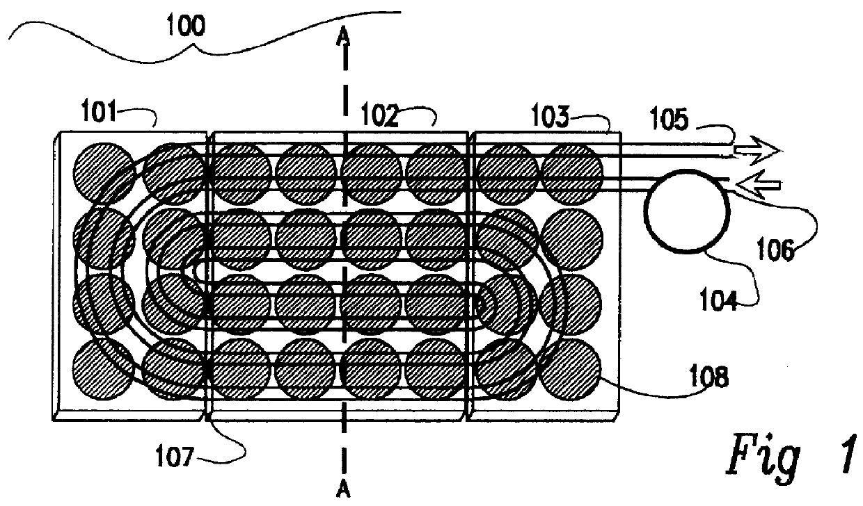
This embodiment provides one or more arrays of solar cells at the focus of a solar concentrator, each cell being in thermal contact with a water cooled surface that provides cooling means for the array so that during conversion of sunlight into electricity the array is kept cooler than it would be if no means for cooling existed. Its output is higher--the band gap of a silicon P-N junction rising as the temperature of the junction drops. We understand that for silicon, temperatures of over 65 deg C. result in a significant fall in output and hence if the invention is to be used for both heat and for electricity output then its temperature may be maintained somewhere between heat sink temperature and 65 degrees C. In any case, our example fluid circulation system is not built to withstand pressure and hence could not support coolant of over about 100 deg C. (if water-based). The actual temperature may be optimised for eff...

example 2

Heated Volumes of Air, for Drying, for Example

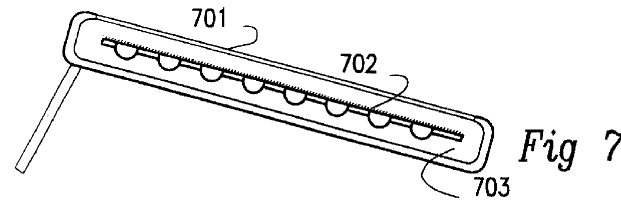
In this alternative, we provide the invention in a form in which air is heated, and usually moved, in an energy-efficient manner. One embodiment is as a portable hot-air drier or "kiln" for drying timber, grain, or other agricultural produce.

The drier (see FIG. 8) includes supports 809 holding up a roof structure 801 which is adapted to collect light and heat. Some of the light is converted to electricity. The heat collection means may for example comprise a system of channels carrying piped heat-carrying fluid which percolates beneath a substrate supporting solar cells (or just a black layer if sufficient electricity is available from a portion of the available area) and carries heat arriving from incident radiation away to a heat exchanger through which ambient air is drawn before passage past the material to be dried. Means are provided to remove the heat from the roof and inject it into moving air, so that warmed moving air, having t...

example 3

Providing Cooled Air

Some produce, or other items, may be better if kept in a cooled air space and in this situation a heat pump in reverse, powered by photovoltaic cells as before, (or one driven by a heat engine) may remove heat from air within a space.


PUM


Abstract

PCT No. PCT / NZ95 / 00084 Sec. 371 Date Feb. 28, 1997 Sec. 102(e) Date Feb. 28, 1997 PCT Filed Sep. 14, 1995 PCT Pub. No. WO96 / 08683 PCT Pub. Date Mar. 21, 1996A solar concentrator for producing usable power as heat and / or electricity uses a self-steering heliostat 1502 to concentrate solar radiation 1509 onto an absorbing surface such as, or including, a solar cell array 1511 capable of absorbing power from the radiation, meanwhile removing heat (such as from long-wave infra-red radiation or resistive losses) from the surface with fluid heat transfer means 1503, 1504, then making effective use of that low-grade heat. Thus the solar cell array is kept relatively cool and a larger proportion of the solar energy incident on the reflector unit is used. The invention uses electricity 1506 from the solar cells to move a transporting fluid through a heat exchanger 1504. Excess electricity may be available for local storage or use 1510, or feeding 1512 to the power distribution grid. Applications include warming swimming pools 1501, heating hot-water supplies using excess electricity, or warming, lighting and ventilating open spaces.

Description

This invention relates to improvements in the capture and use of solar energy, wherein energy captured in a heliostat is used as "low-grade" heat and optionally as electricity, produced in a symbiotic relationship.Solar energy has not, as yet, approached its potential for use because of the costs associated with capturing it in a widely useful form. While a type of solar panels can warm water and some architectural constructions capture the sun's heat to warm a space, these capture devices are rather limited in their diversity. Another type of solar panel is adapted to convert light into electricity, but the capital cost of these has prevented their widespread use.Often a desire to warm an article, a mass of material, or a place is linked to a need to apply other forms of energy to it as well. For example one might want to heat the interior of a building and also supply moving air and lighting, and perhaps electricity in a conventionally usable voltage and frequency. One might want ...

Claims


Application Information

Patent Timeline
Patent Type & Authority Patents(United States)
IPC IPC(8): F03G6/00F03G6/06F24J2/10F24J2/06F24J2/30F24J2/04H01L31/052H01L31/058F24J2/54F24S10/30F24S10/70F24S20/20F24S23/70F24S23/71H01L31/024H01L31/054H02S40/44
CPCF24J2/07F24J2/1047F24J2/12F24J2/54H01L31/052H01L31/0547H02S40/44Y02E10/41Y02E10/46Y02E10/47Y02E10/52Y02E10/60Y02E10/42H01L31/0521F24S23/71F24S23/80F24S20/20F24S30/40F24S23/74Y02E10/40
Inventor JOHNSON, COLIN FRANCIS
Owner JOHNSON COLIN FRANCIS
Why Eureka
Try Eureka