Electrical card connector

a technology of electrical cards and connectors, applied in the direction of coupling devices, coupling devices, coupling parts engagement/disengagement, etc., can solve the problem of inability to efficiently push and pull the electrical cards

Inactive Publication Date: 2009-04-14
HON HAI PRECISION IND CO LTD
View PDF7 Cites 3 Cited by
  • Summary
  • Abstract
  • Description
  • Claims
  • Application Information

AI Technical Summary

Benefits of technology

[0008]Accordingly, an object of the present invention is to provide an electrical card connector including an ejector, a pin member of which is effectively prevented from disengaging away from heart-shaped slot.

Problems solved by technology

For large length of the resilient pieces, there may be small stress that the resilient pieces can't effectively keep the movable ends of the two pin members in the hear-shaped slots and we can't efficiently push and pull the electrical card.

Method used


Image

  • Electrical card connector
  • Electrical card connector
  • Electrical card connector

Examples


Embodiment Construction

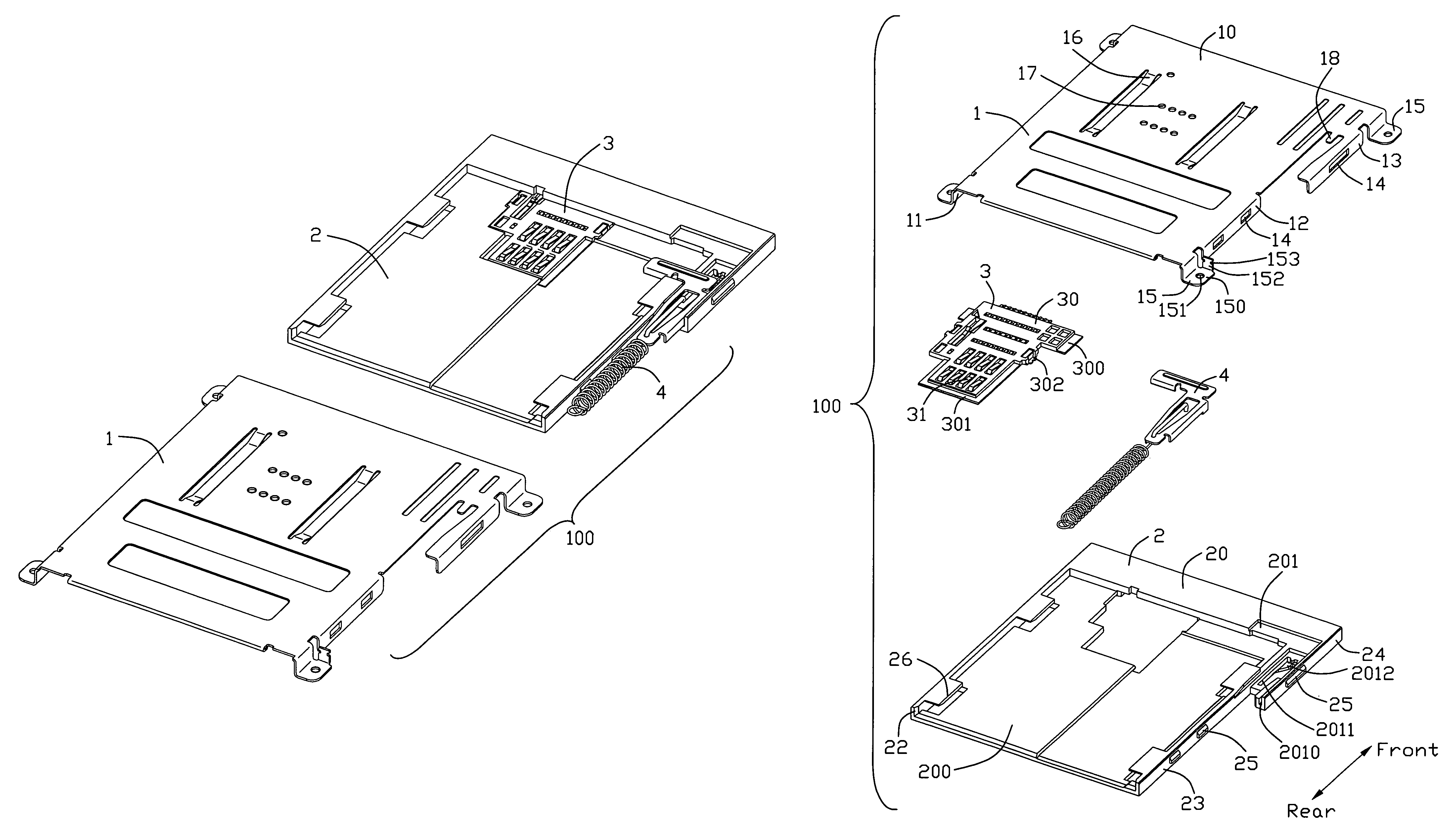
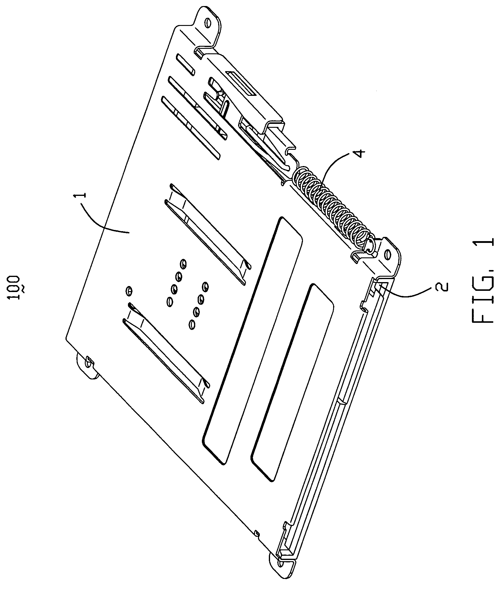
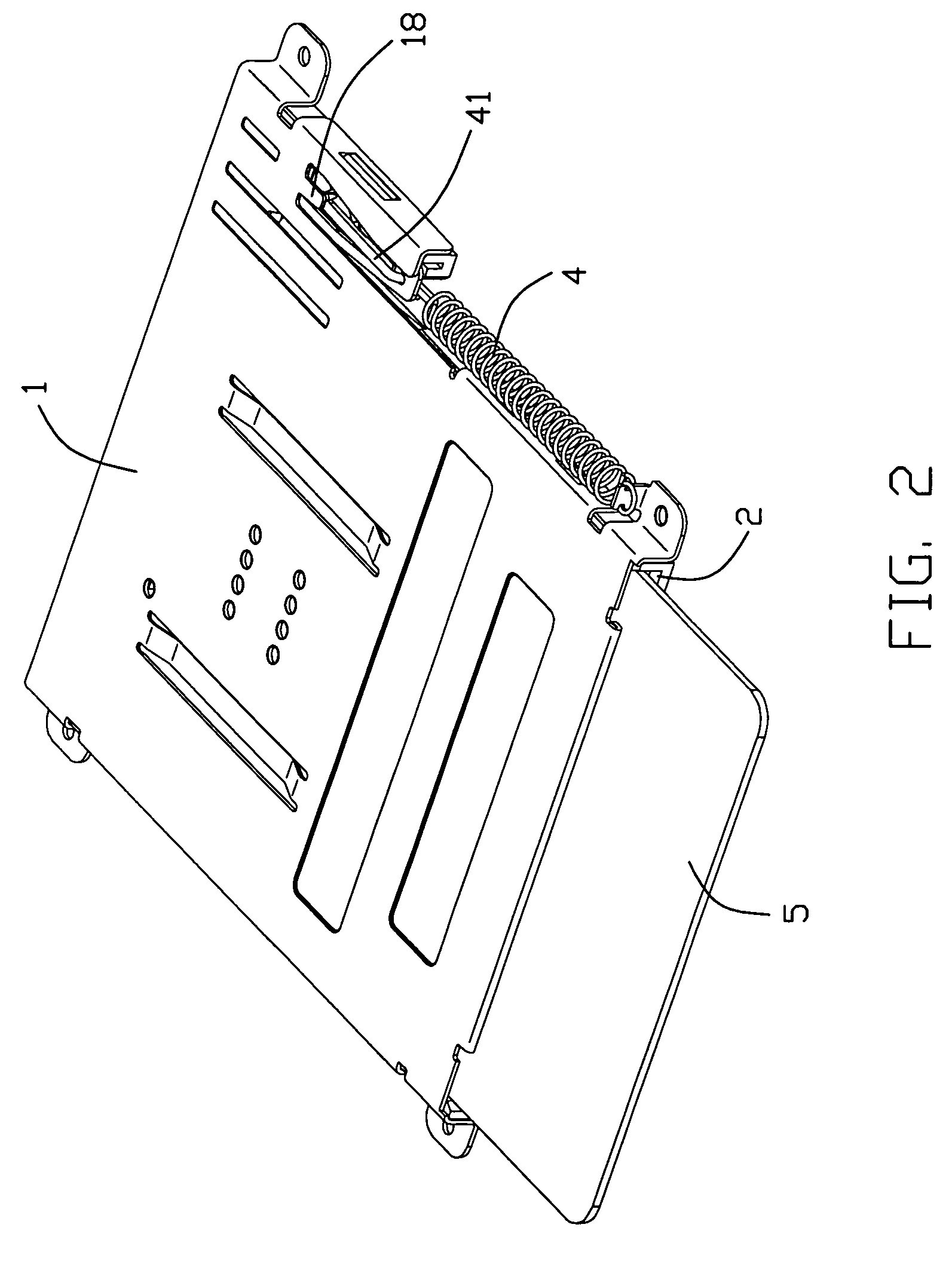
[0019]Referring to FIGS. 1-8, an electrical card connector 100, assembled on a PCB (not shown), comprises a metal shield 1, an insulating housing 2, a terminal module 3 received in the insulating housing 2 and an ejector 4 assembled on the metal shield 1 and the insulating housing 2. The metal shield 1 associates with the insulating housing 2 to define a receiving room (not labeled) for receiving an electrical card 5, and accordingly, a card insertion / ejection direction is also defined.

[0020]Referring to FIG. 5, the metal shield 1 comprises a base 10, a first lateral wall 11, a second lateral wall 12 and a third lateral wall 13. A pair of depressed pieces 16, extending along the card insertion / ejection direction, are formed in the middle of the base 10. A plurality of holes 17 are defined on the base 10 and between the pair of depressed pieces 16. The first lateral wall 11 extends vertically and downwardly from an edge of the base 10. The second lateral wall 12 and the third lateral...


PUM


Abstract

An electrical card connector (100) includes an insulating housing (2), a plurality of terminals (31) received in the insulating housing, a metal shield (1) associated with the insulating housing to define a card receiving room and an ejector (4) including a slider pin (41). A heart-shaped channel (2012) is recessed on the insulating housing and forms a pair of front-to-back extending channels and a pair of inclined channels, which respectively connect with the front-to-back extending channels and communicate with each other. The slider pin is movably received in the heart-shaped channel. The metal shield forms a resilient piece (18) pressing against the slider pin just at the time of the slider pin located at the jointing point of the inclined channels of the heart-shaped channel.

Description

BACKGROUND OF THE INVENTION[0001]1. Field of the Invention[0002]The present invention relates generally to an electrical card connector, and particularly to an electrical card connector with an ejector.[0003]2. Description of Related Arts[0004]An electrical card connector has been widely used for achieving data transmission between an electrical card and a corresponding electronic appliance (e.g., cellular phones, personal computers, PDAs, digital cameras and digital audiovisual apparatuses), according to a very fast development of an electronic field. In order to draw the electrical card out of the card connector conveniently, the electrical card connector usually has an ejector to eject the electrical card. An electrical card connector, shown as U.S. Pat. No. 7,267,565, includes a conventional ejector having a slider, a pin member, a resilient element and an ejecting member for contacting and ejecting an electrical card directly. The slider defines a heart-shaped slot recessed dow...

Claims


Application Information

Patent Timeline
Patent Type & Authority Patents(United States)
IPC IPC(8): H01R13/62
CPCH01R13/65802H01R13/635H01R13/6582H01R2201/16
Inventor TING, CHIEN-JEN
Owner HON HAI PRECISION IND CO LTD
Why Eureka
Try Eureka