Bearing assembly

a technology of bearings and components, applied in the direction of mechanical devices, hubs, transportation and packaging, etc., can solve the problems of noise generation and damage, and achieve the effect of effectively preventing from disengaging

Inactive Publication Date: 2010-07-20
JTEKT CORP
View PDF22 Cites 6 Cited by
  • Summary
  • Abstract
  • Description
  • Claims
  • Application Information

AI Technical Summary

Benefits of technology

[0009]The invention offers the following advantage. In a state where the cover member is fixedly fitted in the end of the outer ring member, the annular member is disposed at the inside surface of the fitting engagement portion of the cover while the engaging portion of the annular member is engaged with the cover member. Therefore, if an excessive difference of thermal expansions or thermal shrinkages results from the different linear expansion coefficients of the cover member formed from the resin material and the annular member formed from the metal material, there is no fear that the annular member may disengage from the cover member. Accordingly, the cover member may be effectively prevented from readily disengaging from the outer ring member even though the fitting engagement portion of the cover member is not increased in the fitting engaging force with respect to the outer ring member or if the fitting engaging force is decreased.
[0010]According to another aspect of the invention, the engaging portion may be a projecting portion formed by radially outwardly projecting a part of the annular member. According to still another aspect of the invention, the projecting portion may be a bent portion formed by bending an end (a vehicular-outer-side end or a vehicular-inner-side end) of the annular member in a radially outward direction of the outer ring member. In a case where the engaging portion of the annular member is constituted by the arc-like projecting portion formed by radially outwardly projecting a part of the annular member or constituted by the bent portion (projecting portion) radially outwardly bent and extended linearly, the annular member may be firmly engaged with the cover member and be effectively prevented from disengaging from the cover member. If the bent portion is particularly embedded in the cover member, this bent portion serves as a kind of anchor. Hence, the core is prevented from being displaced in the axial direction of the outer ring member and disengaging from the cover, even if the binding strength between the cover and the core is decreased due to temperature fluctuations. Accordingly, the cover is able to maintain its fitting or engaging force, so that the cover is prevented from being displaced from the outer ring member or disengaging from the outer ring member.
[0011]It is preferred that a portion belonging to the fitting engagement portion and making contact with the inside surface of the outer ring member as fitted therein has a vehicular-outermost-side region in the axial direction of the outer ring member substantially aligned with the projecting portion with respect to the axial direction of the outer ring member. In the synthetic-resin cover, the fitting engagement portion with respect to the inside surface of the outer ring member is tapered (the portion (indicated by 115a in FIG. 5) fitted in the inside surface of the outer ring member is expanded radially outwardly) due to thermal shrinkage after molding. However, a distal end portion of the fitting engagement portion, which has a great interference with the outer ring member, is aligned with the projecting portion (bent portion) providing a great fitting engaging force (the positions being aligned in the axial direction of the outer ring member), whereby an even greater fitting engaging force may be imparted to the cover. Thus, the cover is assuredly prevented from disengaging from the inside surface of the outer ring member.
[0012]The engaging portion may be an engaging hole radially extended through the annular member. In a case where the engaging portion is constituted by the engaging hole radially extended through the annular member, the resin material may be filled in the engaging hole of the annular member when the annular member is insert-molded in the cover member. Therefore, the annular member may be more firmly bound to the cover member, so as to be effectively prevented from disengaging from the cover member.

Problems solved by technology

Furthermore, the disengaged core 247 may interfere with another component, producing noises or causing damage thereto.

Method used


Image

  • Bearing assembly
  • Bearing assembly
  • Bearing assembly

Examples


Embodiment Construction

[0020]A bearing assembly according to an embodiment of the invention will hereinbelow be described in details with reference to the accompanying drawings.

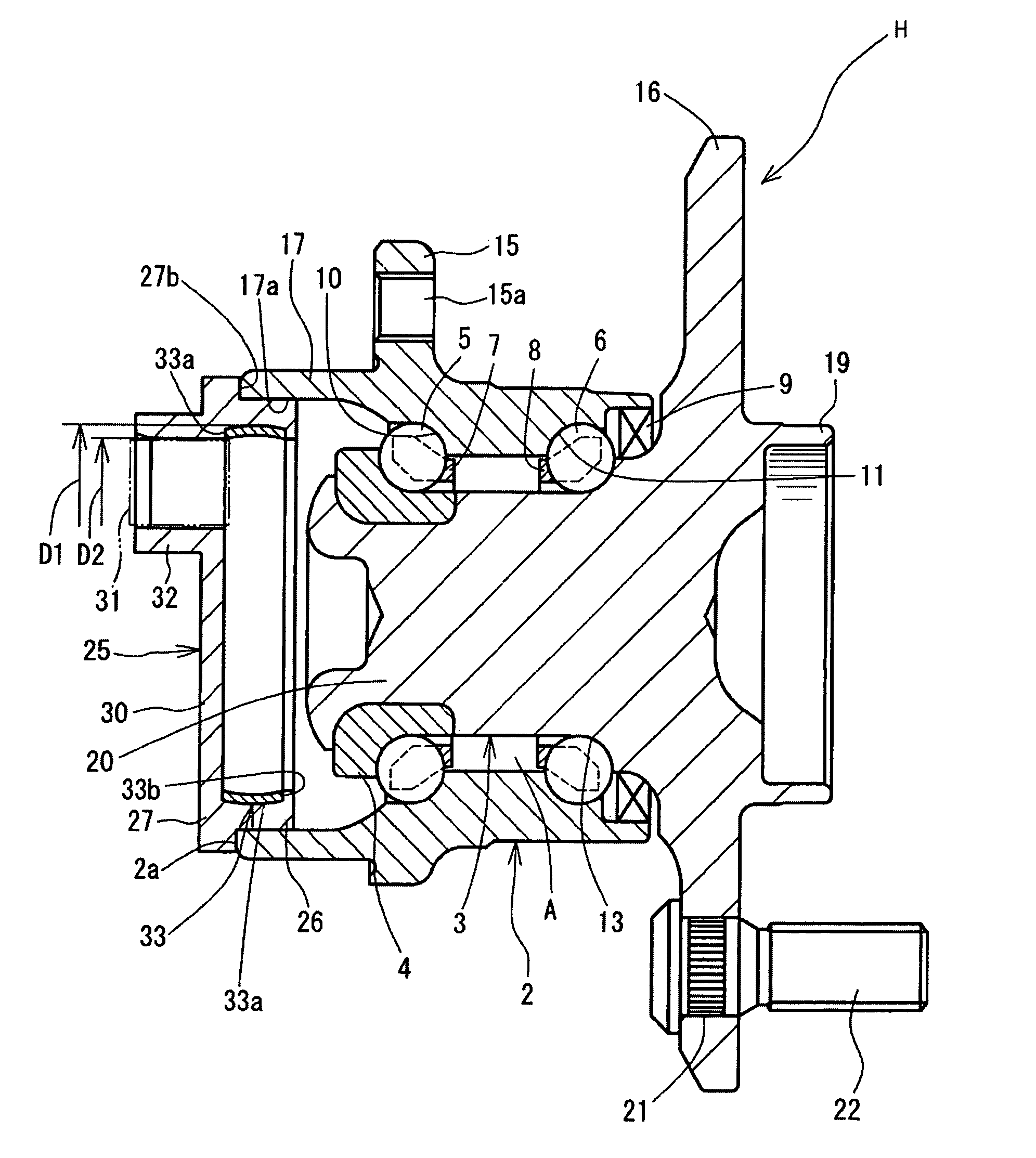
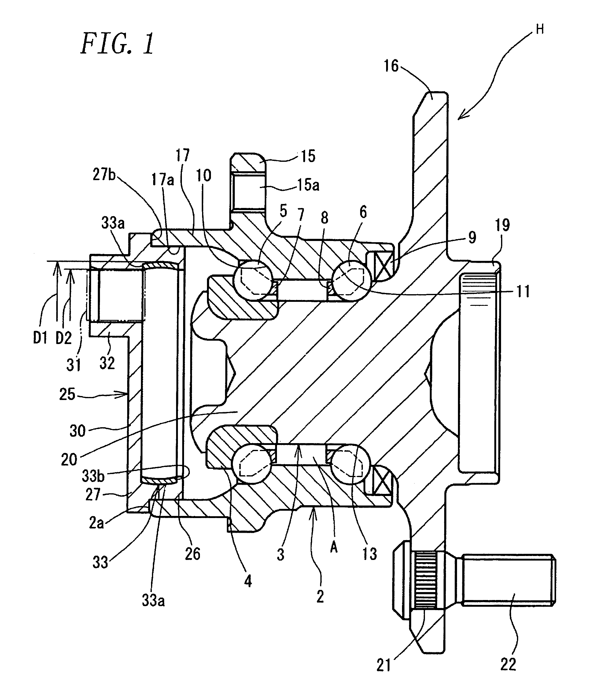
[0021]FIG. 1 is a longitudinal sectional view showing a wheel rolling bearing assembly H (hereinafter, simply referred to as “bearing assembly”) according to one embodiment of the invention. In FIG. 1, the right-hand side represents a vehicular outer side (wheel side) of the bearing assembly H, whereas the left-hand side represents a vehicular inner side (the opposite side to the wheel). The bearing assembly H is constituted as a double-row outward angular contact ball bearing designed to carry an automotive driven wheel. The bearing assembly H includes: an outer ring member 2; a hub spindle 3; an inner ring 4; a plurality of rolling elements 5, 6; two cages 7, 8; and a seal 9. The hub spindle 3 and the inner ring 4 constitute an inner ring member disposed on an inside surface of the outer ring member 2. The outer ring member 2 inc...


PUM


Abstract

[Problems] A bearing assembly is provided which is designed to prevent a core (metal annular member), used in a synthetic-resin cover, from disengaging from the cover.[Means for Solving Problems] A bearing assembly H includes: a synthetic-resin cover 25 fitted in an inside surface of a vehicular-inner-side end of an outer ring member 2, and a metal annular member 33 disposed on an inside surface of a fitting engagement portion 26 of the cover 25, the fitting engagement portion being fitted in the inside surface of the outer ring member 2. The annular member 33 includes an engaging portion 33a in engagement with the cover 25.

Description

TECHNICAL FIELD[0001]The present invention relates to a bearing assembly. More particularly, the invention relates to a bearing assembly wherein a synthetic-resin cover is fit in an inside surface of an outer ring member constituting the bearing assembly.BACKGROUND ART[0002]Conventionally, a rolling bearing assembly has been widely used for rotatably carrying a wheel under a body of an automotive vehicle. As shown in FIG. 6, such a bearing assembly generally includes: an outer ring member 233 fixed to the vehicle body and possessing double raceway surfaces formed on an inside surface thereof; an inner ring member 235 located radially inwardly of the outer ring member 233 in a coaxial relation therewith and adapted for rotation as possessing double raceway surfaces formed on an outside surface thereof; and two rows of rolling elements 236 rollably interposed between the raceway surfaces of the outer ring member 233 and the inner ring member 235. The inner ring member 235 includes: a ...

Claims


Application Information

Patent Timeline
Patent Type & Authority Patents(United States)
IPC IPC(8): F16C33/78
CPCB60B7/0013B60B7/061B60B27/00B60B27/0005B60B27/0068B60B27/0084F16C33/783F16C33/723F16C43/04F16C41/007B60B27/0094F16C19/186F16C2326/02
Inventor AIDA, TOMOYUKIYANO, HIROSHITSUMURA, KATSUNORI
Owner JTEKT CORP
Why Eureka
Try Eureka