Mount for firearms

a mount and firearm technology, applied in the field of firearms, can solve the problems of affecting the precise position of the accessories with respect to the firearm, the inability to adjust the orientation of the accessory, and the existing accessory mount directly securable to the firearm

Active Publication Date: 2009-04-21
DEXTRAZE SERGE
View PDF9 Cites 35 Cited by
  • Summary
  • Abstract
  • Description
  • Claims
  • Application Information

AI Technical Summary

Benefits of technology

[0009]It is therefore an aim of the present invention to provide an accessory mount for releasably securing at least one accessory to a firearm which allows for adjustment of the accessory about two axes.
[0010]It is another aim of the present invention to provide an accessory mount for releasably securing at least one accessory to a firearm which automatically adjusts an azimuth of the accessory when the angle of elevation thereof is varied to compensate for a lateral drift of the firearm.
[0011]It is a further aim of the present invention to provide an accessory mount for releasably securing at least one accessory directly on a firearm which includes a system for dampening the recoil force produced by the firearm.
[0013]Also in accordance with the present invention, there is provided an accessory mount for releasably securing at least one accessory to a firearm, the mount comprising a base portion attachable to the firearm, a body portion engaged to the base portion to be slidable along a first axis substantially parallel to a firing direction of the firearm, an attachment portion connected to the body portion for releasably receiving the at least one accessory, and a dampener system connected to the base and body portions, the dampener system acting along the first axis to dampen a recoil force produced by the firearm.

Problems solved by technology

A disadvantage of such mounts is that the precision of the position of the accessories with respect to the firearm is influenced by the positioning of the firearm on the cradle or support.
Also, existing accessory mounts directly securable to firearms usually provide no adjustment, or a very limited adjustment, of an orientation of the accessory with respect to the firearm.

Method used


Image

  • Mount for firearms
  • Mount for firearms
  • Mount for firearms

Examples


Embodiment Construction

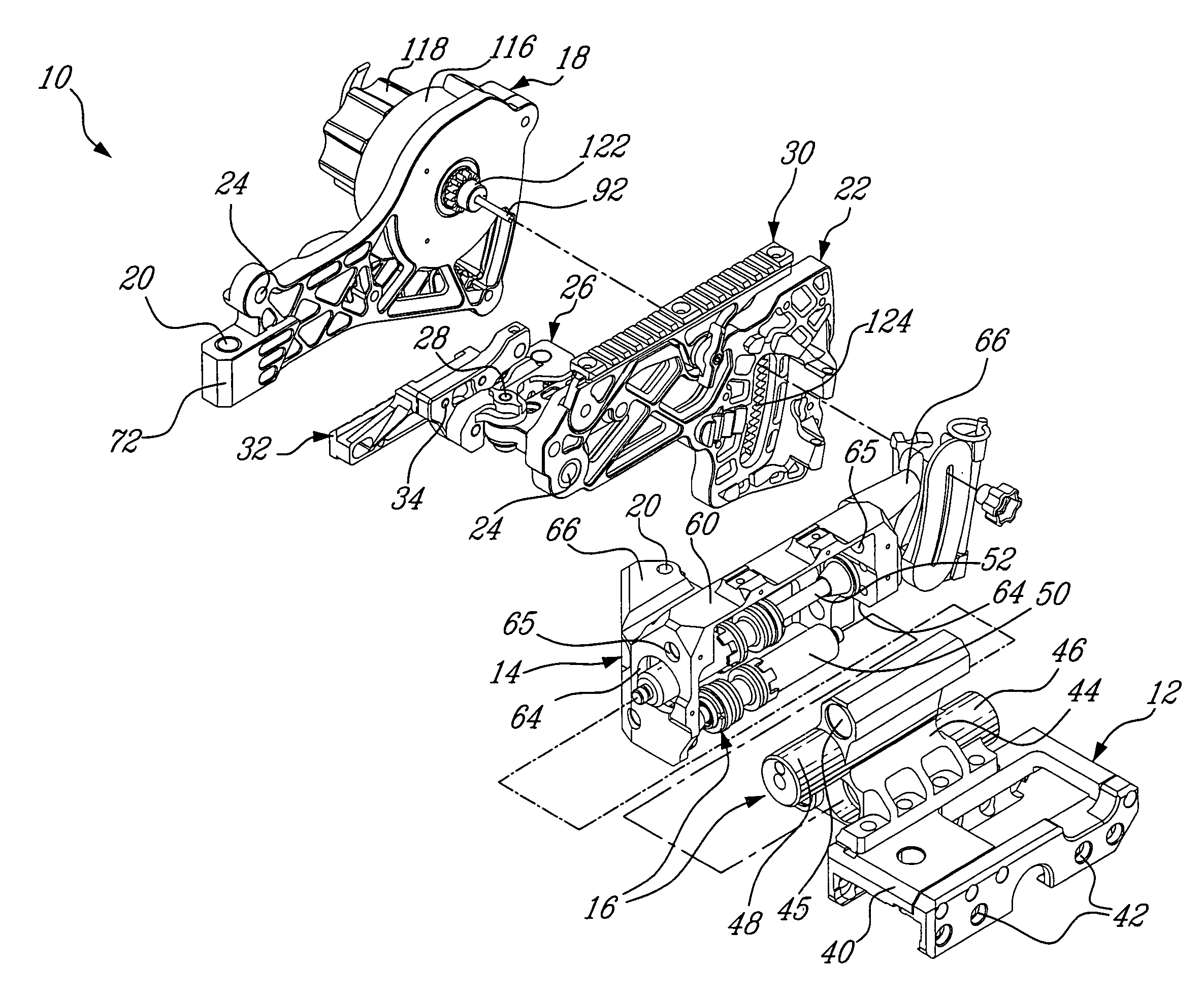
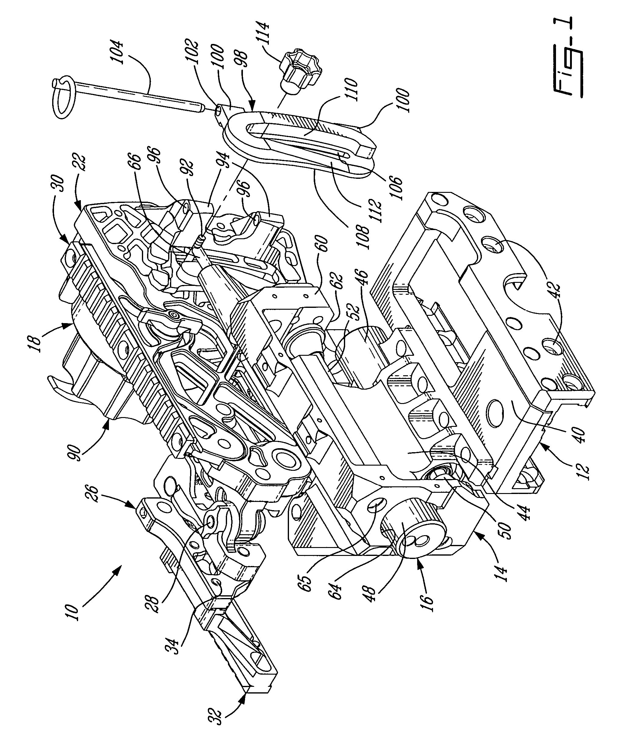
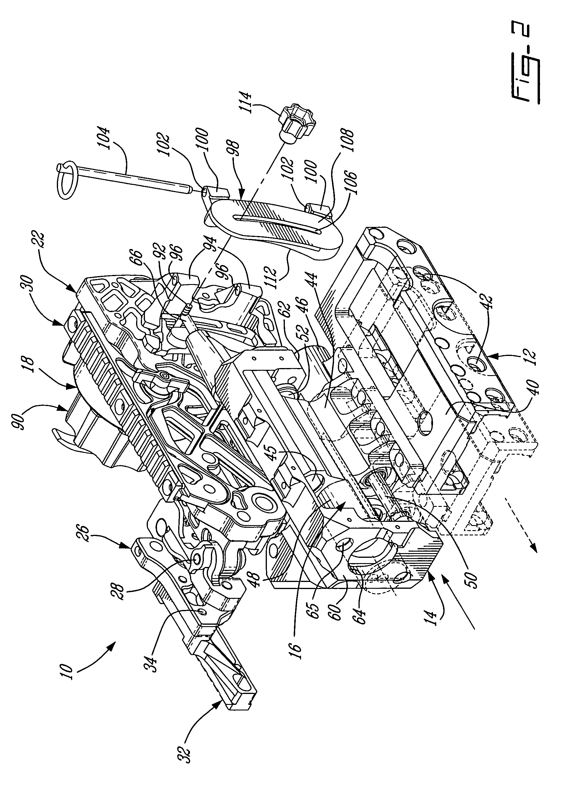
[0026]Referring now generally to FIGS. 1, 2 and 10, an accessory mount according to a preferred embodiment of the present invention is shown at 10. The mount 10 comprises a base 12 and a body 14 which are slidingly connected together through a dampening system 16 to form a connecting portion of the mount 10. The mount 10 also comprises an attachment portion including a first element 18 connected to the body 14 by a first pivot 20, a second element 22 connected to the first element 18 by a second pivot 24, and a third element 26 connected to the second element 22 by a third pivot 28.

[0027]The first pivot 20 provides a rotation about an axis perpendicular to the longitudinal axis of the base 12, which corresponds to the firing direction of the firearm, such that the first element 18 rotates in a substantially horizontal plane when the firing direction is substantially horizontal. The second pivot 24 provides a rotation about an axis perpendicular to the axis of the first pivot 20, suc...


PUM


Abstract

A mount comprising a connecting portion attachable to a firearm, a first member connected to the connecting portion to be rotatable about a first axis, a second member connected to the first member to be rotatable about a second axis substantially perpendicular to the first axis, and an attachment system connected to the second member for receiving an accessory. Also, a mount attachable to a firearm and having a dampener system connected to base and body portions thereof, the dampener system acting to dampen a recoil force produced by the firearm. Further, a mount attachable to a firearm and allowing a first rotation varying an azimuth of an accessory and a second rotation varying an angle of elevation of the accessory, and control means adjusting the second rotation to obtain a desired value and automatically producing the first rotation to correct a lateral drift of the firearm.

Description

BACKGROUND OF THE INVENTION[0001]1. Field of the Invention[0002]The present invention relates to firearms and, more particularly, to systems for mounting various accessories to firearms.[0003]2. Background Art[0004]It is well known to use various accessories, such as infrared and night vision scopes, laser spotters and the like, with firearms. In the case of small firearms, such accessories are typically mounted to an accessory mount directly securable to the firearm.[0005]However, in the case of larger firearms producing a significant recoil force, such as the MK-19 grenade machine gun or the M-2HB machine gun, such accessories are usually mounted to an accessory mount securable to the cradle or another fixed support of the firearm. This eliminates the effect of the recoil force on the accessory, thus minimizing the risks of injury to the operator. One example of such a mount is the MK RANGER, which adapts to the MK-64 or MK-93 cradle used with the MK-19 grenade machine gun, and re...

Claims


Application Information

Patent Timeline
Patent Type & Authority Patents(United States)
IPC IPC(8): F41G1/387
CPCF41G1/393F41C27/00F41G11/002
Inventor DEXTRAZE, SERGE
Owner DEXTRAZE SERGE
Why Eureka
Try Eureka