Clamp

a technology of clamping and clamping rods, which is applied in the field of clamping rods, can solve the problems of pipe deformation, large diameter pipe deformation, and pipe vibration of automobiles, and achieve good clamping state

Inactive Publication Date: 2009-05-12
TOYOTA JIDOSHA KK
View PDF15 Cites 31 Cited by
  • Summary
  • Abstract
  • Description
  • Claims
  • Application Information

AI Technical Summary

Benefits of technology

[0009]The invention thus aims to provide a clamp which, when holding a plurality of pipes having different outer diameters, is able to hold all of the pipes with appropriate clamping force such that there is no fear of the pipes deforming, and is also able to achieve an excellent vibration absorption effect.
[0013]Making the compressibility of the elastic bodies with respect to all of the pipes having different diameters the same in this way enables an appropriate clamping force to be obtained for all of the pipes without too much or too little stress being applied to the pipes of different diameters. As a result, the pipes will not be deformed. Moreover, even if settling of the elastic bodies occurs due to deterioration over time, the decrease in binding force caused by that settling of the elastic bodies would be uniform for all of the pipes, such that the clamp hold would not loosen.
[0015]According to the invention, in a clamp which includes a pair of clamp members that sandwich a plurality of pipes, each clamp member including an elastic body having a plurality of concave portions formed therein and a reinforcing plate fixed to the outer side surface of the elastic body, when holding a plurality of pipes having different outer diameters, the dimensions of each portion of the elastic bodies are set so that the compression ratio of the elastic bodies is the same for all of the pipes. As a result, all of the pipes are able to be uniformly held with an appropriate clamping force so that the pipes will not deform. Moreover, the binding force will not decrease in one area more than in another even if settling of the elastic bodies occurs due to deterioration over time. As a result, a good clamping state is able to be maintained over an extended period of time.

Problems solved by technology

These pipes are subject to vibrations of the automobile.
Furthermore, the vibration absorption effect may not be able to be achieved.
If, on the other hand, the tightening allowance is appropriate for the small diameter pipe, then the force applied to a large diameter pipe ends up being excessive, possibly resulting in deformation of the large diameter pipe.
There is also a possibility of the small diameter pipe becoming deformed depending on amount of compression of the elastic body.
Moreover, if the tightening allowance is the same for each pipe, the decrease in binding force between pipes of different diameters may become uneven if the pipes settle on the elastic body as it deteriorates over time.
As a result, the hold of the clamp on the large diameter or small diameter pipe would become loose, such that the vibration absorption effect would no longer be able to be achieved.

Method used


Image

  • Clamp
  • Clamp
  • Clamp

Examples


first embodiment

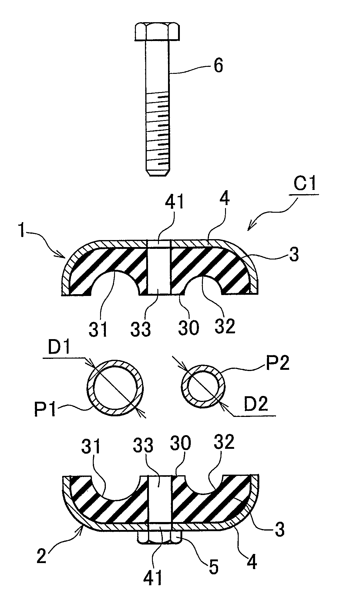
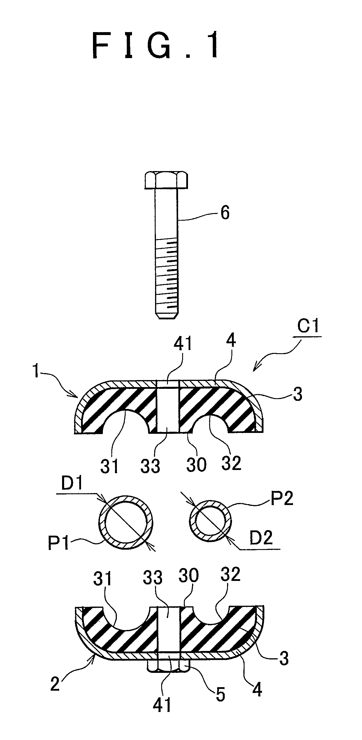
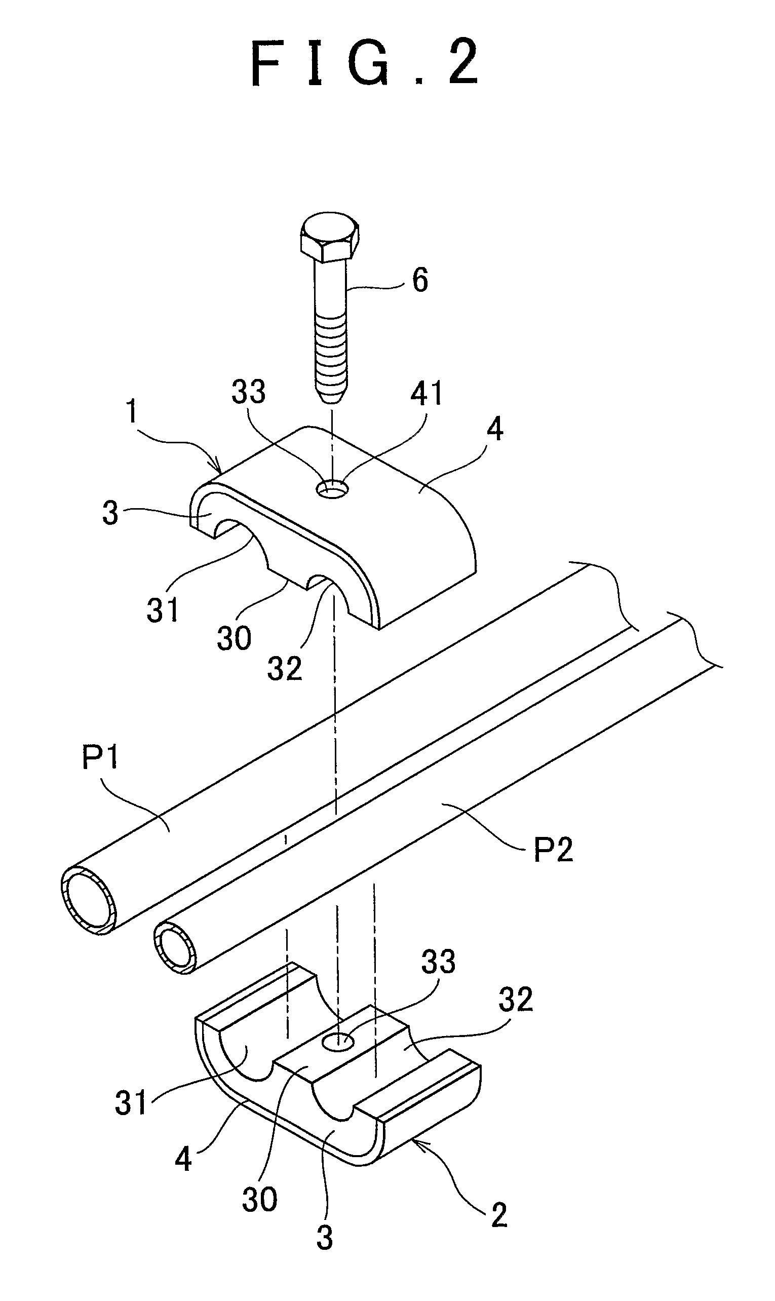
[0030]FIG. 1 is a vertical cross-sectional view illustrating a clamp according to a first exemplary embodiment of the invention in a disassembled state. FIG. 2 is an exploded perspective view of that clamp. FIG. 3 is a front elevational view, and FIG. 4 is a perspective view, illustrating the clamp shown in FIG. 1 as it is used.

[0031]The clamp in this example is a clamp C1 which holds pipes such as fuel pipes and brake pipes in an automobile. The clamp C1 includes a pair of clamp members 1 and 2 which sandwich two pipes P1 and P2 having different diameters. Each clamp member 1 and 2 includes an elastic holding body 3 and a reinforcing plate 4.

[0032]Each elastic holding body 3 and 3 is a manufactured product of chloroprene rubber. These two elastic holding bodies 3 and 3 are both formed symmetrical such that overall a generally rectangular block shaped member is formed when mating faces 30 of the elastic holding bodies 3 and 3 are matched up with each other. Two semi-circular concave...

second embodiment

[0045]The above example describes a clamp which holds two pipes P1 and P2. The invention is not limited to this, however, i.e., the number of pipes connected and held may alternatively be three or more. For example, the invention may also be applied to a clamp C2 which connects and holds four pipes P1 to P4 having different diameters, as described in a second exemplary embodiment illustrated in FIGS. 6 to 9.

[0046]In this case, when the diameters of the pipes P1, P2, P3, and P4 which are held by the clamp are made D1, D2, D3, and D4, respectively, and the curvature radius of each concave portion 131, 132, 133, and 134 of an elastic holding body 103 of each clamp member 101 and 102 is made R1, R2, R3, and R4, respectively, and the distances from mating faces 130 of the elastic holding bodies 103 and 103 to the inner side surfaces of reinforcing plates 104 are made L11, 12, . . . , L41, and L42, respectively, then the dimensions of each portion of the elastic holding bodies 103 and 103...

third embodiment

[0049]FIG. 10 is a vertical cross-sectional view illustrating a clamp according to a third exemplary embodiment of the invention in a disassembled state. FIG. 11 is a front elevational view, and FIG. 12 is a perspective view, of the clamp shown in FIG. 10 as it is used.

[0050]Clamp C3 in this example is characterised in that, in the structure shown in FIGS. 1 to 5 described above, elastic holding bodies 213 and 223 as well as reinforcing portions 214 and 224 of a pair of clamp members 201 and 202 are asymmetrical with respect to one another, and the distance L11 (see FIG. 13) of one of the elastic holding bodies 213 (i.e., the elastic holding body on the upper side in FIG. 10) is shorter than the distance L12 (see FIG. 13) of the other elastic holding body 223 (i.e., the elastic holding body on the lower side in FIG. 10). The other structure is the same as that of clamp C1 shown in FIGS. 1 to 5.

[0051]In this way, even if the pair of elastic holding bodies 213 and 223 are asymmetrical...


PUM


Abstract

In a clamp having a pair of clamp members which sandwich a plurality of pipes having cylindrical cross-sections of different diameters, each of the clamp members including an elastic body having a plurality of concave portions formed therein and a reinforcing plate fixed to an outer side surface of the elastic body, the dimensions of each portion of the elastic bodies are set such that the compression ratio of the elastic bodies with respect to all of the pipes is made the same. For example, when the diameters of two pipes having different outer diameters are made D1 and D2, the curvature radii of the concave portions of the elastic bodies are made R1 and R2, and the distances from mating faces of the elastic bodies to the reinforcing plates are made L11, . . . , L22, then the dimensions of each portion of the elastic bodies are set so as to satisfy the relationship [(D1−2R1) / (L11+L12−2R1)=(D2−2R2) / (L21+L22−2R2).

Description

INCORPORATION BY REFERENCE[0001]This is a 371 national phase application of PCT / IB20056 / 002132 filed 4 Jul. 2005, claiming priority to Japanese Patent Application No. 2004-216303 filed 23 Jul. 2004, the contents of which are incorporated herein by reference.FIELD OF THE INVENTION[0002]The invention relates to a clamp which holds a pipe through which a fluid flows in a fuel system, brake system, cooling system, or the like in an automobile or the like. More particularly, the invention relates to a clamp that is suitable for preventing vibrations from reaching a plurality of pipes by connecting and holding the pipes.BACKGROUND OF THE INVENTION[0003]Pipes such as fuel pipes, brake pipes, and cooling system pipes are typically disposed in an engine room and the like of an automobile. These pipes are subject to vibrations of the automobile. In order to prevent those vibrations from reaching the pipes, a method has been employed in which the pipes are held by clamps.[0004]One related pipe...

Claims


Application Information

Patent Timeline
Patent Type & Authority Patents(United States)
IPC IPC(8): F16L3/22F16L3/223F16L3/237F16L55/035
CPCF16L3/2235F16L3/237F16L55/035
Inventor HASHIMOTO, TAKESHI
Owner TOYOTA JIDOSHA KK
Why Eureka
Try Eureka