

Bearing retainer and bearing provided with same
A bearing cage and cage technology, which is applied to bearing components, shafts and bearings, bearing cooling, etc., can solve the problems of insufficient impact resistance and limited use range, and achieve improved lubrication effect, weight reduction, and improved impact resistance. Effect
- Summary
- Abstract
- Description
- Claims
- Application Information
AI Technical Summary
Problems solved by technology
Method used
Image


Examples
Embodiment 1
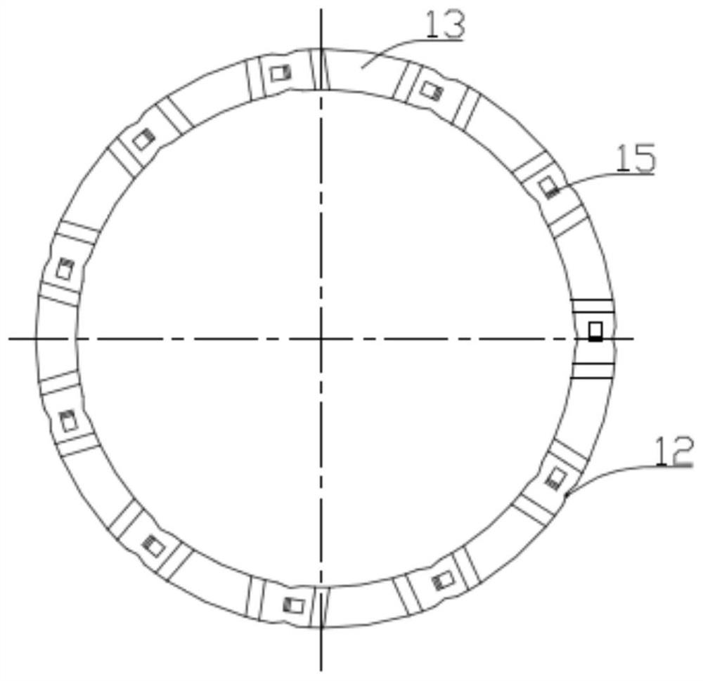
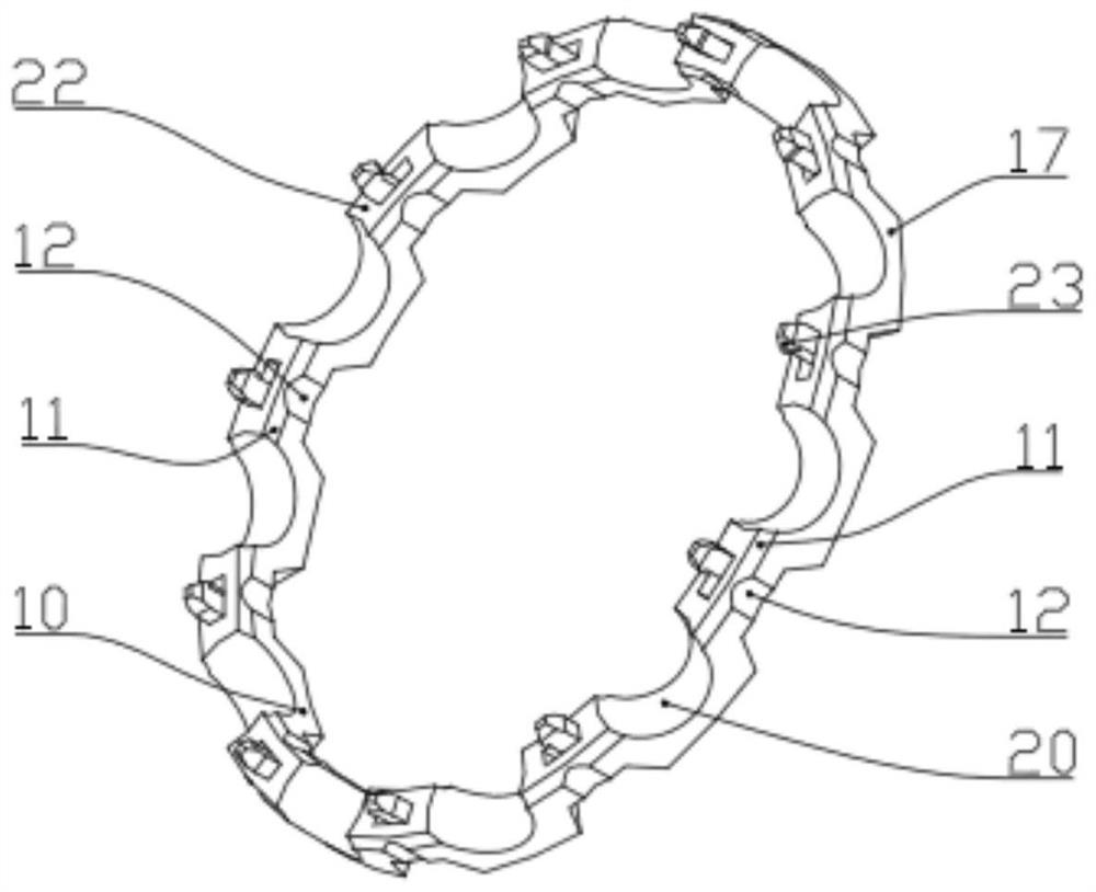
[0030] Such as Figure 1-6 The shown bearing cage includes two identical upper and lower annular half cages, which can be connected up and down in the axial direction, and the connection surface of the two annular half cages is the inner end surface 22, and the two half ring The cages are snap-connected through a plurality of connecting points provided on the inner end surface 22 along the circumferential direction of the ring. After the two half-cages are connected, a plurality of pockets 21 are formed between the two half-cages along the circumferential direction. The inner end surfaces 22 are evenly spaced with pocket-shaped grooves 20 , and the inner end surfaces 22 between adjacent pocket-shaped grooves 20 are all provided with locking connection points. The inner end surface 22 protrudes from the inner end surface 22 and is provided with a locking arm 16, and one side of the locking arm 16 is recessed in the inner end surface 22 to be provided with a locking groove 15, a...
Embodiment 2
[0037] A bearing, the bearing includes any one of the above-mentioned bearing cages. This cage can be used on a bearing as a bearing cage.
[0038] When the above-mentioned bearing cage is used for bearing assembly, first put the fitted bearing on the workbench, and then put a single half cage so that the rolling elements are in the pocket of the cage, and then put it into another cage. When placing one and a half cages and another half cage, it is necessary to ensure that the lock arms and lock grooves of the two half cages correspond to each other, and finally put the bearings with the cages in the corresponding press-fitting equipment for press-fitting. So far, the assembly work of the cage is completed.
[0039] This embodiment specifically relates to the bearing cage described in Embodiment 1, which is mainly used in related bearings with large impact, large vibration, poor heat dissipation, and medium-to-high speed operation.
PUM
 Abstract
Description
Claims
Application Information