Clamp
a technology of clamping and clamping rods, which is applied in the field of clamping rods, can solve the problems of pipe deformation, large diameter pipe deformation, and pipe vibration of automobiles, and achieve good clamping state
- Summary
- Abstract
- Description
- Claims
- Application Information
AI Technical Summary
Benefits of technology
Problems solved by technology
Method used
Image
Examples
first embodiment
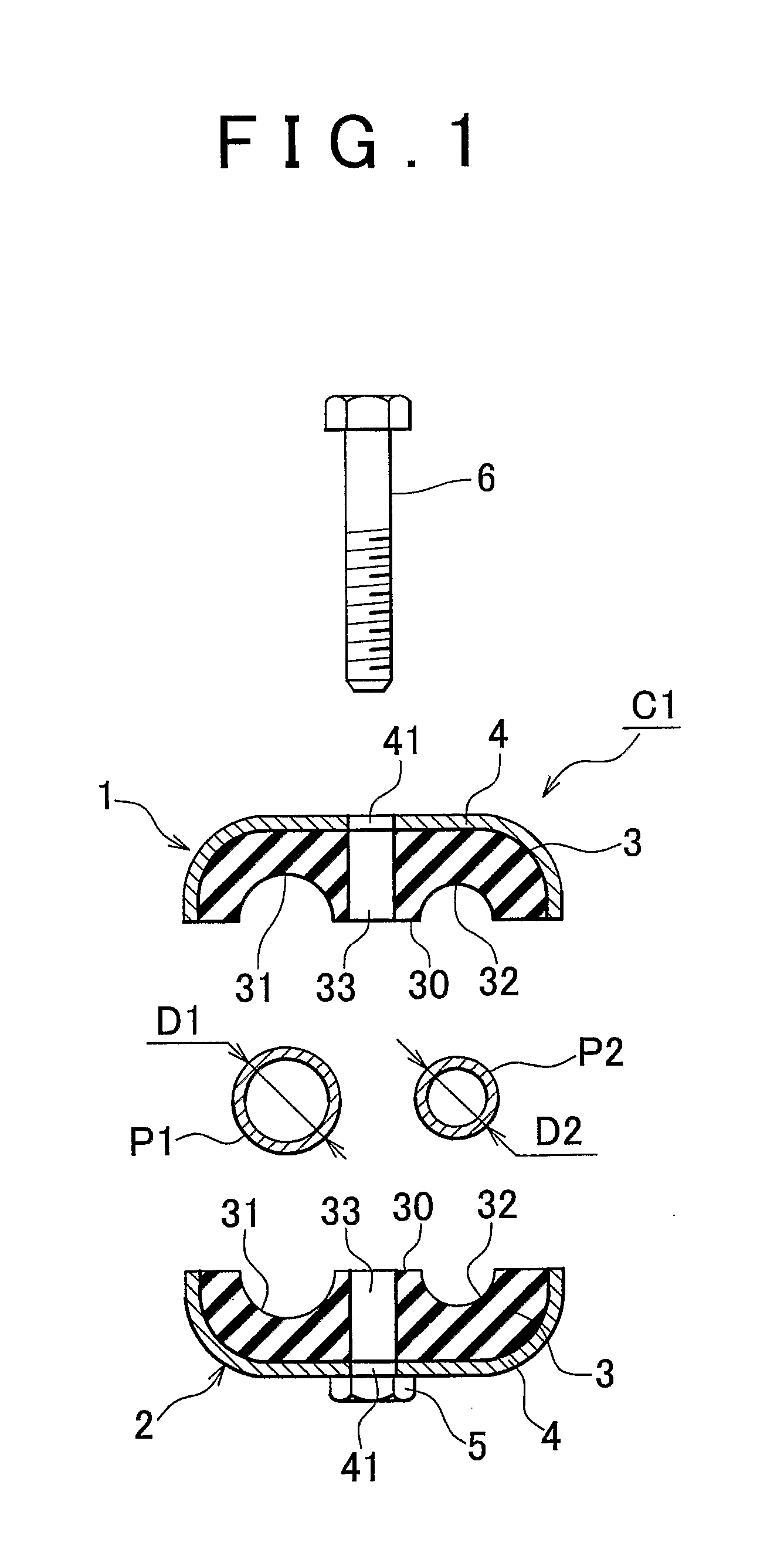
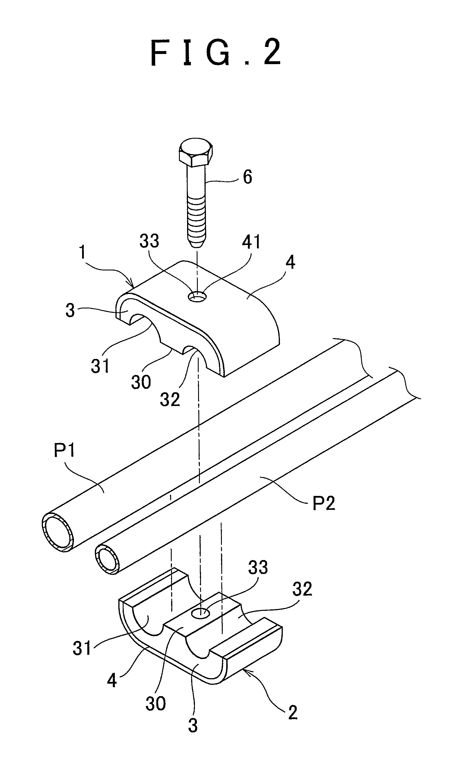
[0030]FIG. 1 is a vertical cross-sectional view illustrating a clamp according to a first exemplary embodiment of the invention in a disassembled state. FIG. 2 is an exploded perspective view of that clamp. FIG. 3 is a front elevational view, and FIG. 4 is a perspective view, illustrating the clamp shown in FIG. 1 as it is used.
[0031] The clamp in this example is a clamp C1 which holds pipes such as fuel pipes and brake pipes in an automobile. The clamp C1 includes a pair of clamp members 1 and 2 which sandwich two pipes P1 and P2 having different diameters. Each clamp member 1 and 2 includes an elastic holding body 3 and a reinforcing plate 4.
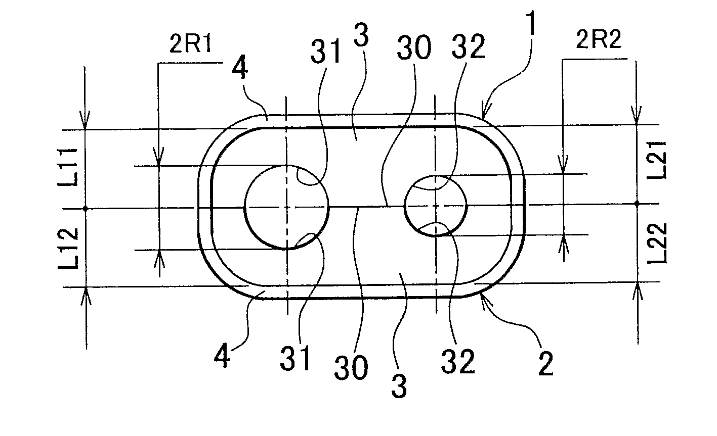
[0032] Each elastic holding body 3 and 3 is a manufactured product of chloroprene rubber. These two elastic holding bodies 3 and 3 are both formed symmetrical such that overall a generally rectangular block shaped member is formed when mating faces 30 of the elastic holding bodies 3 and 3 are matched up with each other. Two semi-circular con...
second embodiment
[0045] The above example describes a clamp which holds two pipes P1 and P2. The invention is not limited to this, however, i.e., the number of pipes connected and held may alternatively be three or more. For example, the invention may also be applied to a clamp C2 which connects and holds four pipes P1 to P4 having different diameters, as described in a second exemplary embodiment illustrated in FIGS. 6 to 9.
[0046] In this case, when the diameters of the pipes P1, P2, P3, and P4 which are held by the clamp are made D1, D2, D3, and D4, respectively, and the curvature radius of each concave portion 131, 132, 133, and 134 of an elastic holding body 103 of each clamp member 101 and 102 is made R1, R2, R3, and R4, respectively, and the distances from mating faces 130 of the elastic holding bodies 103 and 103 to the inner side surfaces of reinforcing plates 104 are made L11, 12, . . . , L41, and L42, respectively, then the dimensions of each portion of the elastic holding bodies 103 and ...
third embodiment
[0049]FIG. 10 is a vertical cross-sectional view illustrating a clamp according to a third exemplary embodiment of the invention in a disassembled state. FIG. 11 is a front elevational view, and FIG. 12 is a perspective view, of the clamp shown in FIG. 10 as it is used.
[0050] Clamp C3 in this example is characterised in that, in the structure shown in FIGS. 1 to 5 described above, elastic holding bodies 213 and 223 as well as reinforcing portions 214 and 224 of a pair of clamp members 201 and 202 are asymmetrical with respect to one another, and the distance L11 (see FIG. 13) of one of the elastic holding bodies 213 (i.e., the elastic holding body on the upper side in FIG. 10) is shorter than the distance L12 (see FIG. 13) of the other elastic holding body 223 (i.e., the elastic holding body on the lower side in FIG. 10). The other structure is the same as that of clamp C1 shown in FIGS. 1 to 5.
[0051] In this way, even if the pair of elastic holding bodies 213 and 223 are asymmetr...
PUM
 Abstract
Description
Claims
Application Information
 - R&D
- Intellectual Property
- Life Sciences
- Materials
- Tech Scout
- Unparalleled Data Quality
- Higher Quality Content
- 60% Fewer Hallucinations
Browse by: Latest US Patents, China's latest patents, Technical Efficacy Thesaurus, Application Domain, Technology Topic, Popular Technical Reports.
© 2025 PatSnap. All rights reserved.Legal|Privacy policy|Modern Slavery Act Transparency Statement|Sitemap|About US| Contact US: help@patsnap.com


