Chin rest for musical instrument

a musical instrument and chin rest technology, applied in the field of chin rests for musical instruments, can solve the problems of difficult to keep a chin rest clamp positioned properly, the need for a tool may not make a full turn, and the process of attaching and/or removing a conventional chin rest to an instrument can be time-consuming and laborious,

Inactive Publication Date: 2009-05-12
BUTTEMER EVAN D
View PDF184 Cites 16 Cited by
  • Summary
  • Abstract
  • Description
  • Claims
  • Application Information

AI Technical Summary

Benefits of technology

[0006]According to another aspect of the present invention, a chin rest for an instrument comprises a body, a first support, a second support, a third support and a chin pad. The first support extends from a first end portion of the body and has at least one clamping member and at least one adjustable feature. The second support extends from a second end portion of the body and has at least one clamping member. The third support extends from the body between the first and second supports. Further, the chin pad coupled to the body. The chin rest is configured such that the clamping members of the first and second supports apply sufficient force to an upper rim of a musical instrument to temporarily clamp the chin rest to the musical instrument when the chin rest is mounted on the musical instrument and the adjustable feature of the first support enables the chin pad to be continuously variably positionable about a predetermined range of the upper rim of the body.

Problems solved by technology

However, the clamp is close to the instrument itself.
Thus, a required tool may not make a full turn when removing or attaching a chin rest from a corresponding instrument.
Thus, the process of attaching and / or removing a conventional chin rest to an instrument can be a time consuming and arduous task.
It can be difficult to keep a chin rest clamp positioned properly during the securement operation described above.
Moreover, if the clamp slips, it is possible that either the clamp or the tool used to tighten or loosen the clamp can scratch or otherwise damage the instrument.

Method used


Image

  • Chin rest for musical instrument
  • Chin rest for musical instrument
  • Chin rest for musical instrument

Examples


Embodiment Construction

[0021]In the following detailed description, reference is made to the accompanying drawings that form a part hereof, and in which is shown by way of illustration, and not by way of limitation, specific aspects of the invention. It is to be understood that changes may be made without departing from the spirit and scope of various embodiments of the present invention.

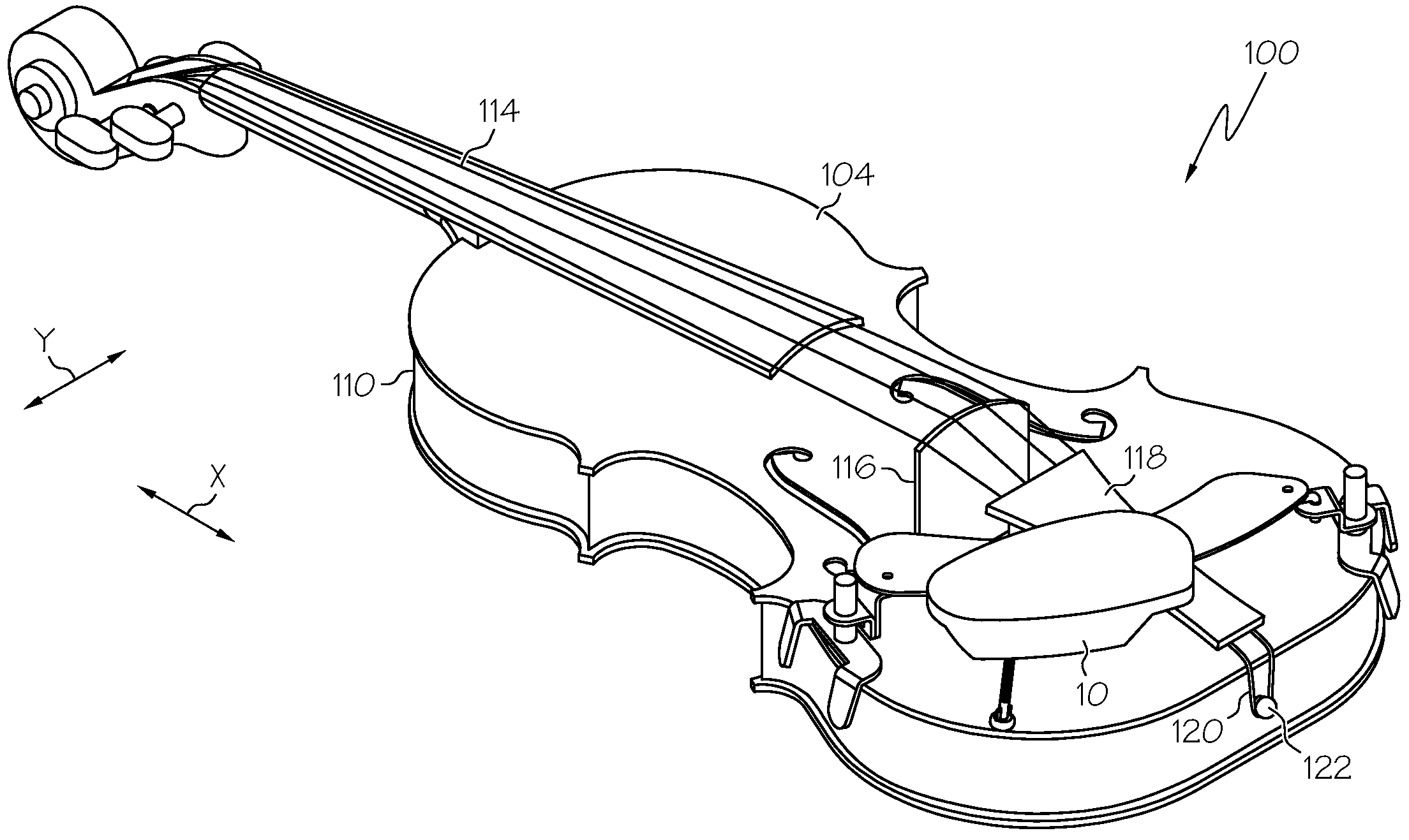
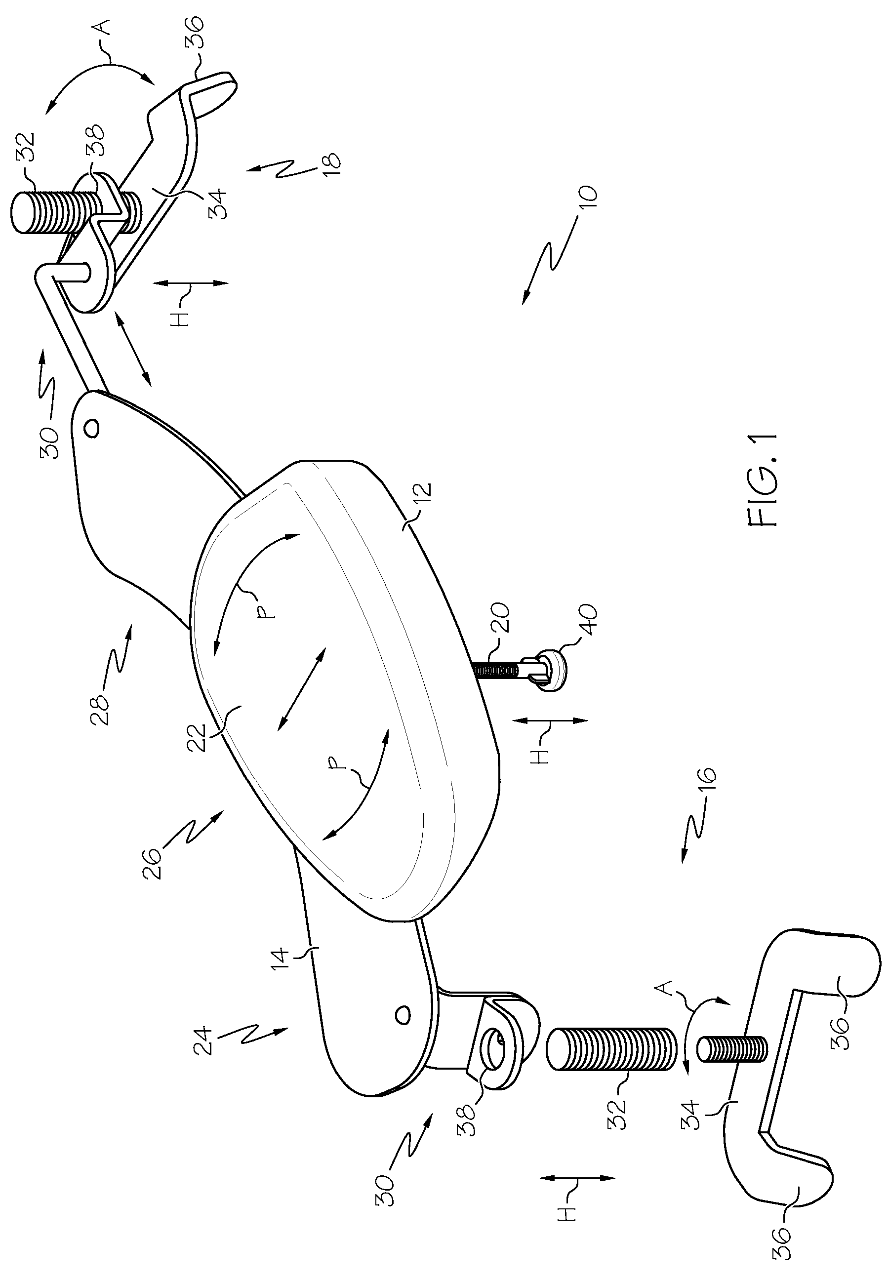
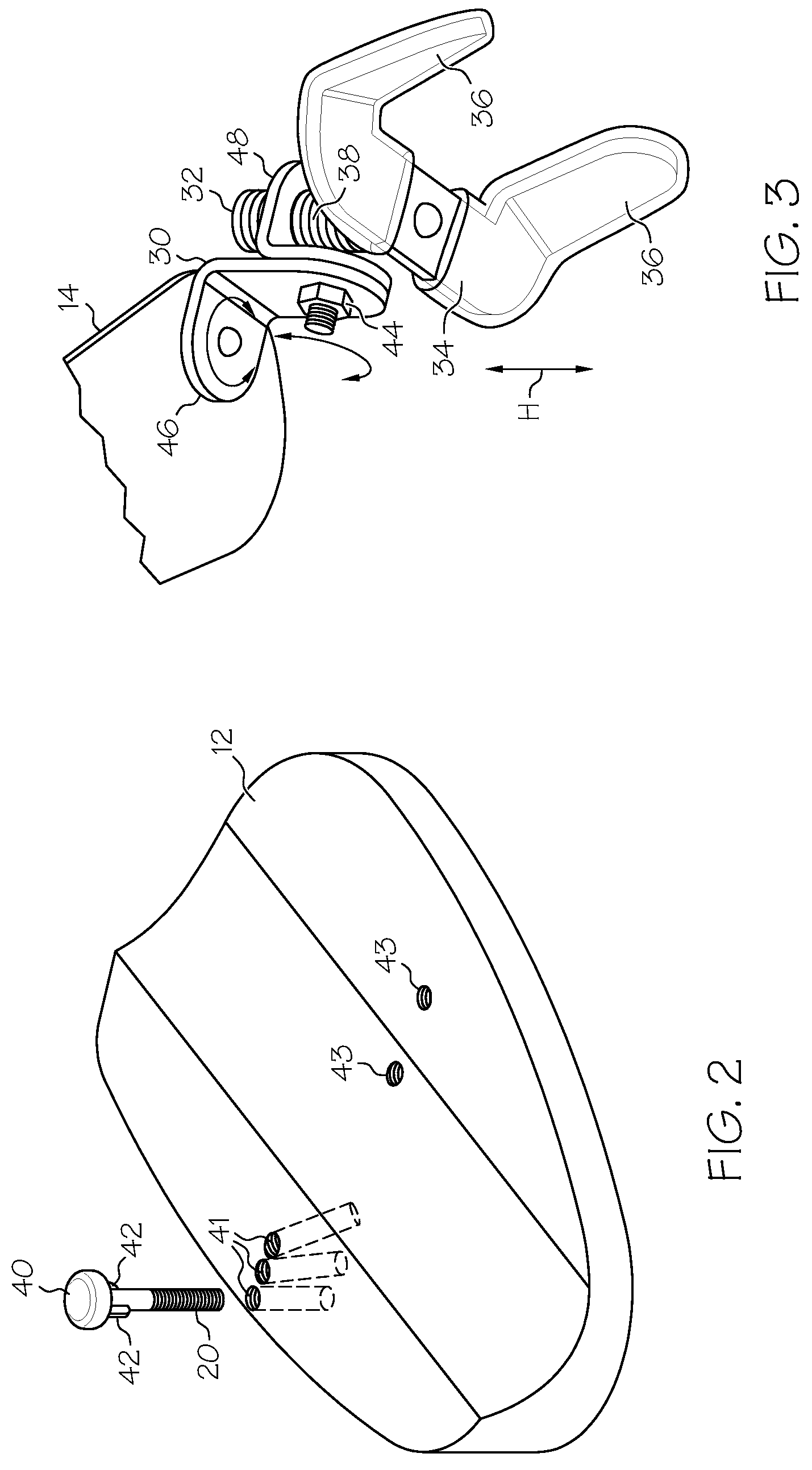
[0022]Referring now to the drawings, and particularly to FIG. 1, a chin rest 10 for use with a musical instrument is illustrated. According to various aspects of the present invention, the chin rest 10 comprises a chin pad 12, a body (also referred to herein as a bridge) 14, a first support 16, a second support 18 and a third support 20. The chin pad 12 includes a contoured support surface 22, such as a generally concave or other suitably shaped portion to receive the chin of a performer. The chin pad 12 and corresponding support surface 22 can be any size and / or shape that accommodates the chin of a performer when the ch...


PUM


Abstract

A chin rest for a musical instrument comprises a body, a first support, a second support, a chin pad and a third support. The first support extends from a first end portion of the body and has at least one clamping member for engaging an upper rim of a musical instrument body. Similarly, the second support extends from a second end portion of the body and has at least one clamping member for engaging the upper rim of the musical instrument body in a position spaced from the first support. The chin pad includes a chin receiving surface for receiving a chin of a performer of the musical instrument, and is coupled to the body. The third support may contact a position along the upper rim of the musical instrument, e.g., between the first and second supports when the chin rest is mounted to a corresponding instrument.

Description

BACKGROUND OF THE INVENTION[0001]The present invention relates in general to chin rests for musical instruments, and more particularly, to a chin rest that provides adjustability, can improve the sonorous tone produced by a corresponding instrument and / or that is conveniently mounted onto and removed from a corresponding instrument.[0002]A conventional chin rest for a musical instrument, such as a violin or viola, comprises a generally arcuate chin pad that is attached to a generally “C” shaped clamp. The chin rest is typically installed on a corresponding instrument such that the clamp grips an edge of a top surface (belly) and an edge of a bottom surface (back) of the instrument near an endpin of the instrument so as to position the chin pad to receive the chin of the performer when the instrument is held in a performance position.[0003]The clamp typically includes an upper clamping member that threadably secures to a lower clamping member using one or more threaded posts and corr...

Claims


Application Information

Patent Timeline
Patent Type & Authority Patents(United States)
IPC IPC(8): G10D1/02
CPCG10D3/18
Inventor BUTTEMER, EVAN D.
Owner BUTTEMER EVAN D
Why Eureka
Try Eureka