
Emergency warning system for approach of right of way vehicle

a technology for emergency warning and right of way vehicles, applied in the direction of variable traffic instructions, road vehicle traffic control, instruments, etc., can solve problems such as potential blockage of emergency vehicles, and achieve the effects of maximizing safety and health of both drivers and others, minimizing the input of emergency warning systems, and maximizing chances

Inactive Publication Date: 2009-05-26
MCKENNA LOUIS H
View PDF30 Cites 13 Cited by
  • Summary
  • Abstract
  • Description
  • Claims
  • Application Information

AI Technical Summary

Benefits of technology

[0028]An advantage of the present invention is that the safety and health of the both the driver and others is maximized. A feature contributing to this advantage is the selection of a common and inexpensive object in which to house the emergency warning system. Since the object is common and inexpensive, chances are maximized that the object, and thus the emergency warning system, will be in the right car at the right time.
[0029]Another advantage of the present invention is cost. Since the inputs and outputs are minimized, the emergency warning system includes a minimum of parts and instructions. The inputs of the emergency warning system can be minimized because merely a specific predefined signal is sought. The outputs of the emergency warning system can be minimized because in one embodiment there is only an audio warning.
[0030]An advantage of the selection of a license plate for housing at least the receiver of an emergency warning system is that the license plate is on an exterior of the vehicle exposed to a maximum extent to a right of way predefined signal being emitted by an emergency vehicle.
[0031]An advantage of the selection of a credit card size housing for inclusion of an emergency warning system is that such a credit card sized housing may be carried in a wallet or purse or attached to a windshield or hung from a rear view mirror.

Problems solved by technology

Such a driver, however, can potentially block an emergency vehicle trying to thread its way through traffic.

Method used


Image

  • Emergency warning system for approach of right of way vehicle
  • Emergency warning system for approach of right of way vehicle
  • Emergency warning system for approach of right of way vehicle

Examples


Embodiment Construction

[0047]The Emergency Warning System 10 in General

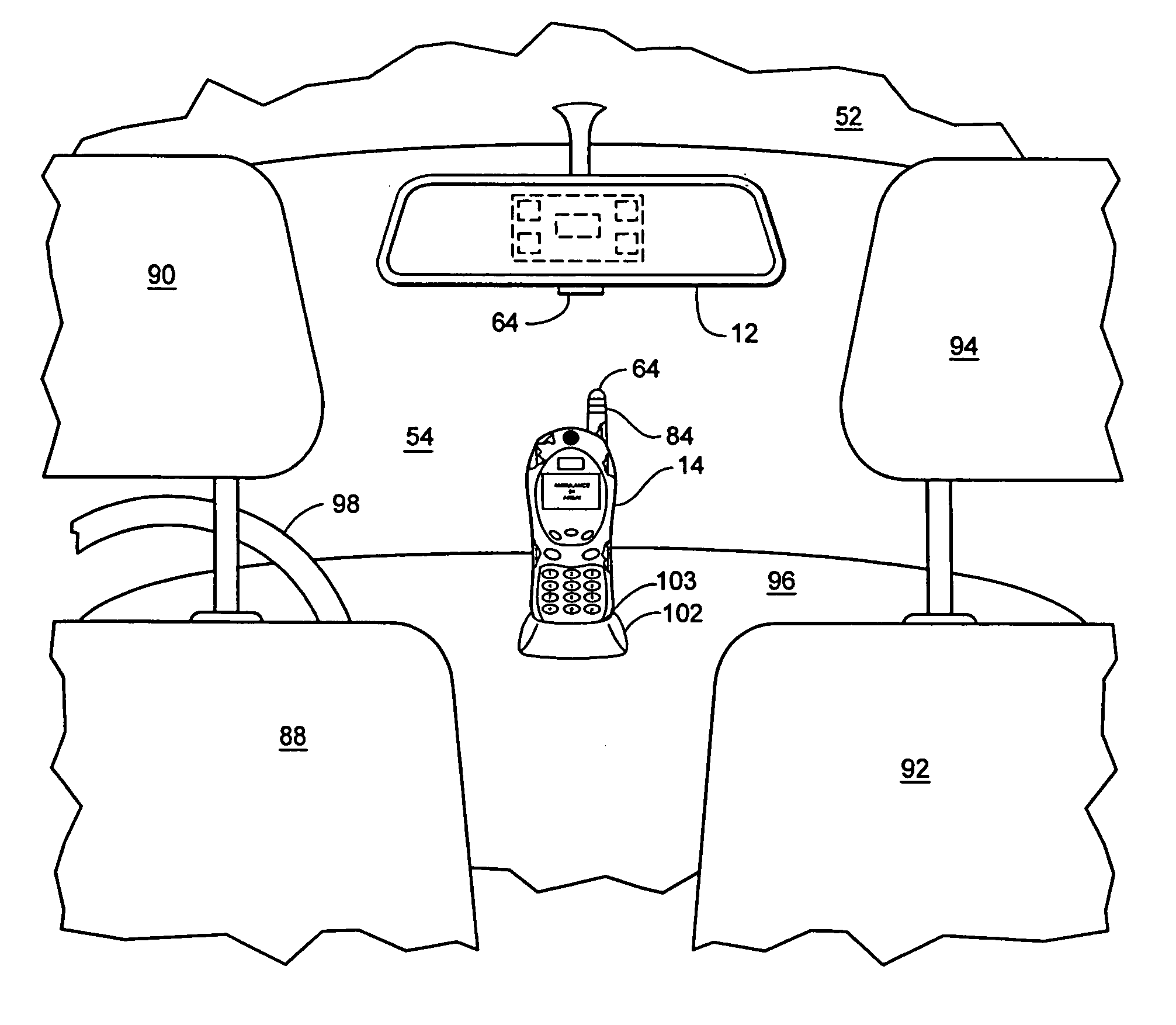
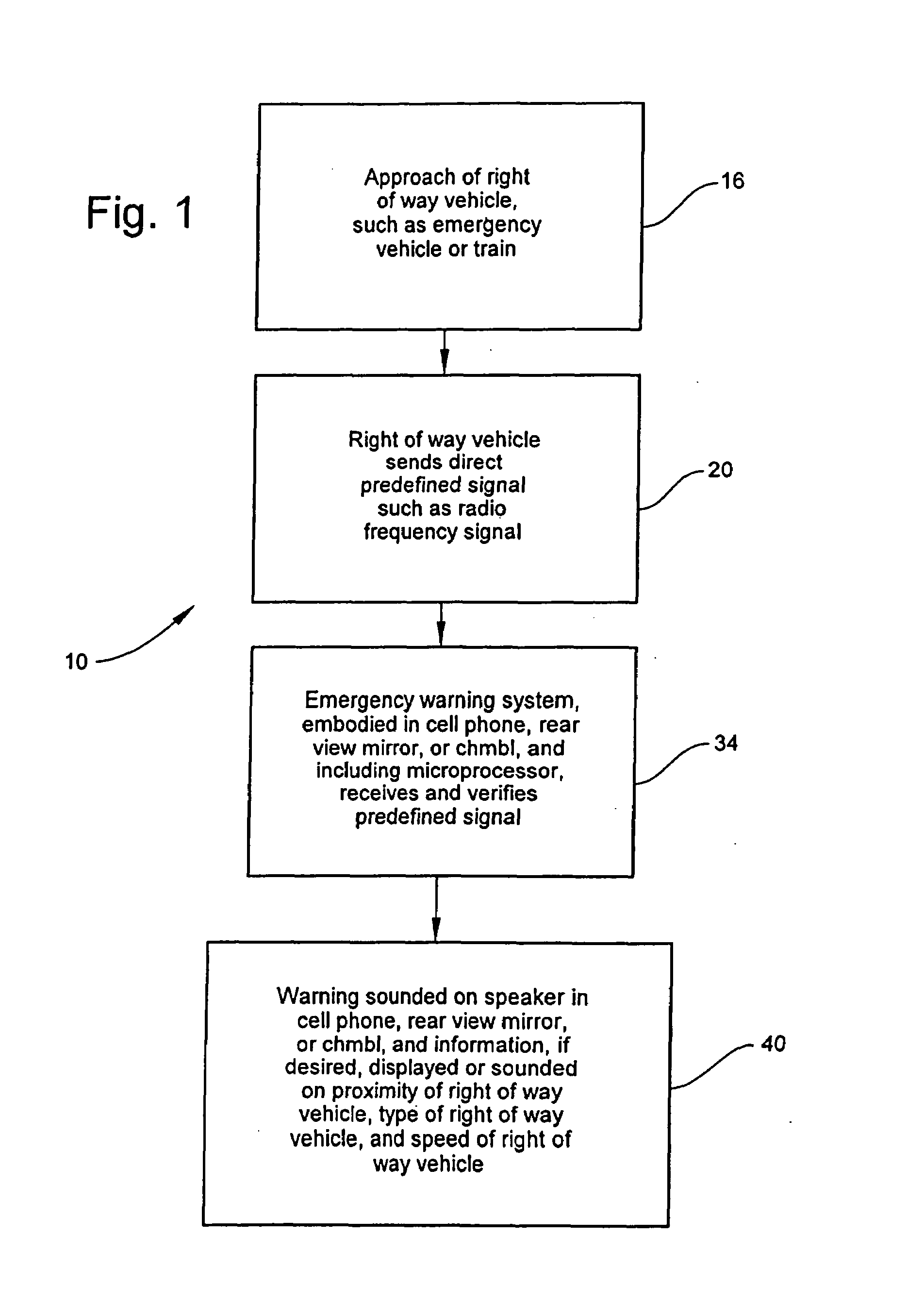
[0048]The present emergency warning system is indicated in general by the reference number 10 in FIG. 1. The emergency warning system 10 can be housed in an automotive rear view mirror 12, as shown in FIGS. 4A and 4B, or a cell phone 14 as shown in FIG. 5, or a CHMBL 15 as shown in FIGS. 6, 7A and 7B, or a telematics unit or system 120 as shown in FIG. 9A, or at least partially in a license plate 200 shown in FIG. 10A, or at least partially in a license plate holder 202 for a license plate 204 shown in FIG. 10B, or at least partially in a stand-alone housing 300 shown in FIG. 11.

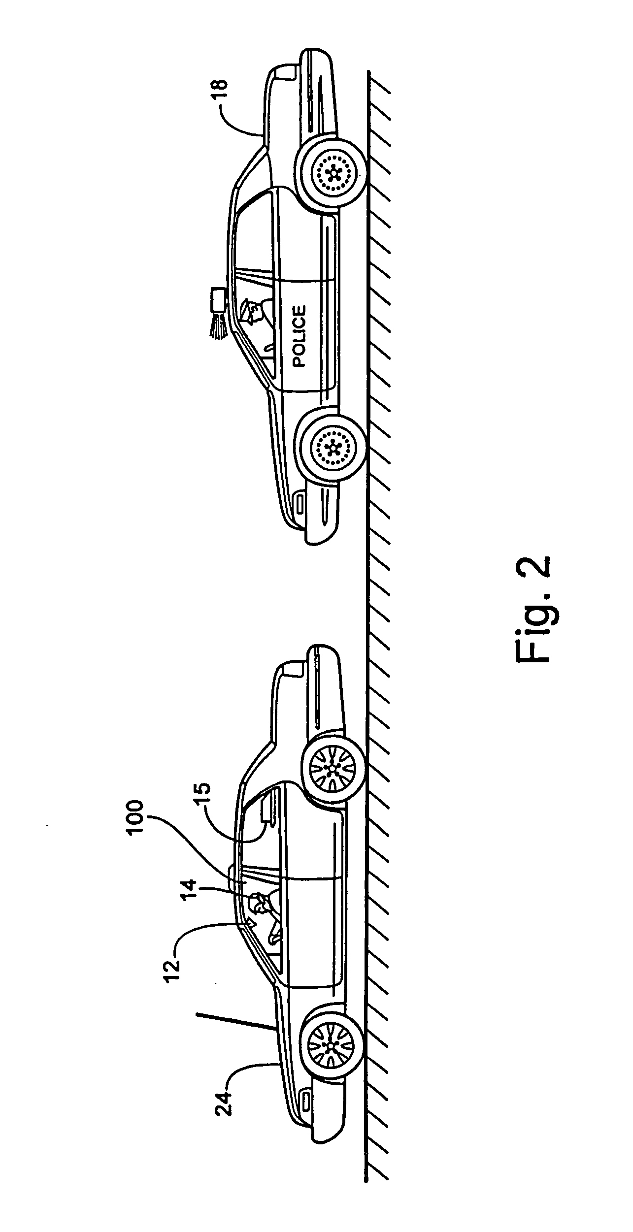
[0049]As shown in FIG. 1, the emergency warning system or method 10 includes the step 16 of warning of an approaching right of way vehicle 18, as shown in FIG. 2. The right of way vehicle 18 shown in FIG. 2 is a police car. The right of way vehicle 18 may be a police car, an ambulance, a fire engine, a train, or another vehicle traveling a relatively high speed...


PUM


Abstract

A common inexpensive device such as an automotive internal rear view mirror, cell phone, CHMBL (center high mounted brake light), license plate or stand-alone housing incorporates an emergency warning system to detect a predefined signal emitted by an right of way vehicle such as an ambulance, police car, fire engine, or train. The right of way vehicle sends out a specific predefined signal to a predefined area. The specific predefined signal is picked up by a receiver of the present emergency warning system. Then, after verification of the specific predefined signal, the emergency warning system emits a warning, preferably an audio warning.

Description

[0001]This application is a continuation-in-part application of U.S. patent application Ser. No. 11 / 435,238 filed May 15, 2006 and claims the benefit thereof under 35 U.S.C. § 120. This application also claims the benefit under 35 U.S.C. 119(e) of U.S. Provisional Patent Application No. 60 / 713,868 filed Sep. 1, 2005. U.S. patent application Ser. No. 11 / 435,238 filed May 15, 2006 and U.S. Provisional Patent Application No. 60 / 713,868 filed Sep. 1, 2005 are hereby incorporated by reference in their entireties into this application.FIELD OF THE INVENTION[0002]The present invention generally relates to emergency warning systems, particularly to emergency warning systems for approach of right of way vehicles, and specifically to such emergency warning systems housed partially or fully in common inexpensive objects such as license plates, internal rear view mirrors, cell phones, and CHMBLs (center high mounted brake light or auxiliary or third rear brake light) or housed partially or full...

Claims


Application Information

Patent Timeline
Patent Type & Authority Patents(United States)
IPC IPC(8): G08G1/00
CPCG08G1/0965
Inventor MCKENNA, LOUIS H
Owner MCKENNA LOUIS H
Learn More