Internal combustion engine having two exhaust gas turbocharger

a technology of exhaust gas and turbocharger, which is applied in the direction of combustion engines, charge feed systems, and addition of non-fuel substances to fuel, etc., can solve the problems of limiting adjustment possibilities and two-stage supercharging not having any direct influence on the exhaust gas behavior of internal combustion engines

Inactive Publication Date: 2009-06-02
DAIMLER AG
View PDF25 Cites 98 Cited by
  • Summary
  • Abstract
  • Description
  • Claims
  • Application Information

AI Technical Summary

Benefits of technology

[0013]This arrangement requires only simple means for adjusting asymmetrical exhaust gas back pressures in the two exhaust lines in the section between the outlet of the cylinders of the internal combustion engine and the exhaust gas turbines. The asymmetry in the exhaust gas back pressures can be utilized for improved exhaust gas recirculation since that exhaust line participates in the recirculation of exhaust gas in which the exhaust gas back pressure exceeds the charge pressure in the intake section in certain operating states while, with the same operating conditions, a pressure which is below the charge pressure can be maintained in the second exhaust line.
[0014]The asymmetry can be achieved with structurally simple means. According to one advantageous embodiment, one of the two exhaust gas turbines is equipped with two separate exhaust gas inlet flows passages via which the exhaust gas is to be fed to the turbine wheel of the respective exhaust gas turbine. The two exhaust gas flows passages are each connected to one of the two separate exhaust lines. Using a different cross-sectional geometry and / or a different size of the two exhaust flow passages it is possible to generate different exhaust gas back pressures in the respective line sections between the internal combustion engine and the inlet to each exhaust gas flow passage.

Problems solved by technology

However, two stage supercharging does not have any direct influence on the exhaust gas behavior of the internal combustion engine.
However, the adjustment possibilities are restricted to regulating the nonreturn valve in the exhaust gas recirculation line.

Method used


Image

  • Internal combustion engine having two exhaust gas turbocharger
  • Internal combustion engine having two exhaust gas turbocharger
  • Internal combustion engine having two exhaust gas turbocharger

Examples


Embodiment Construction

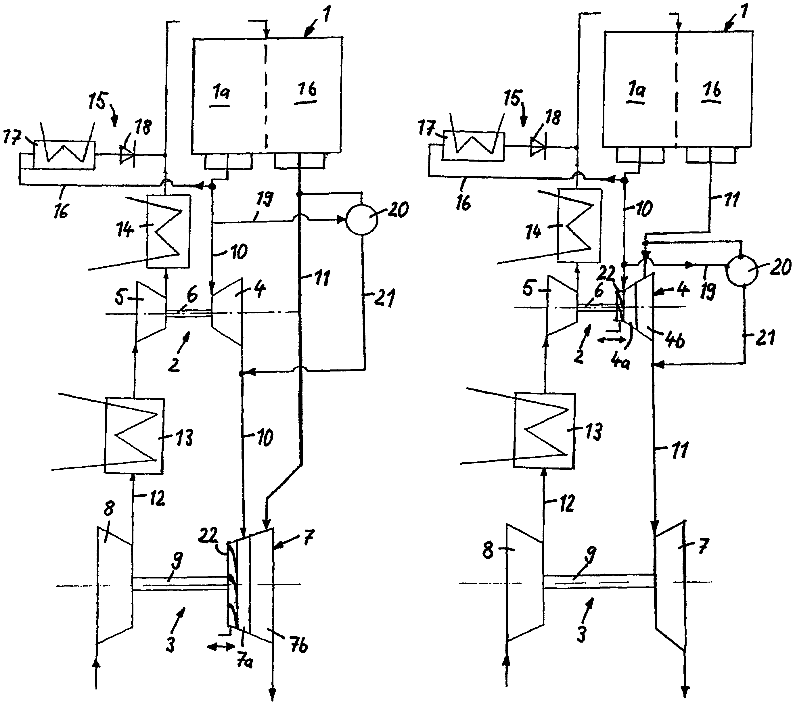
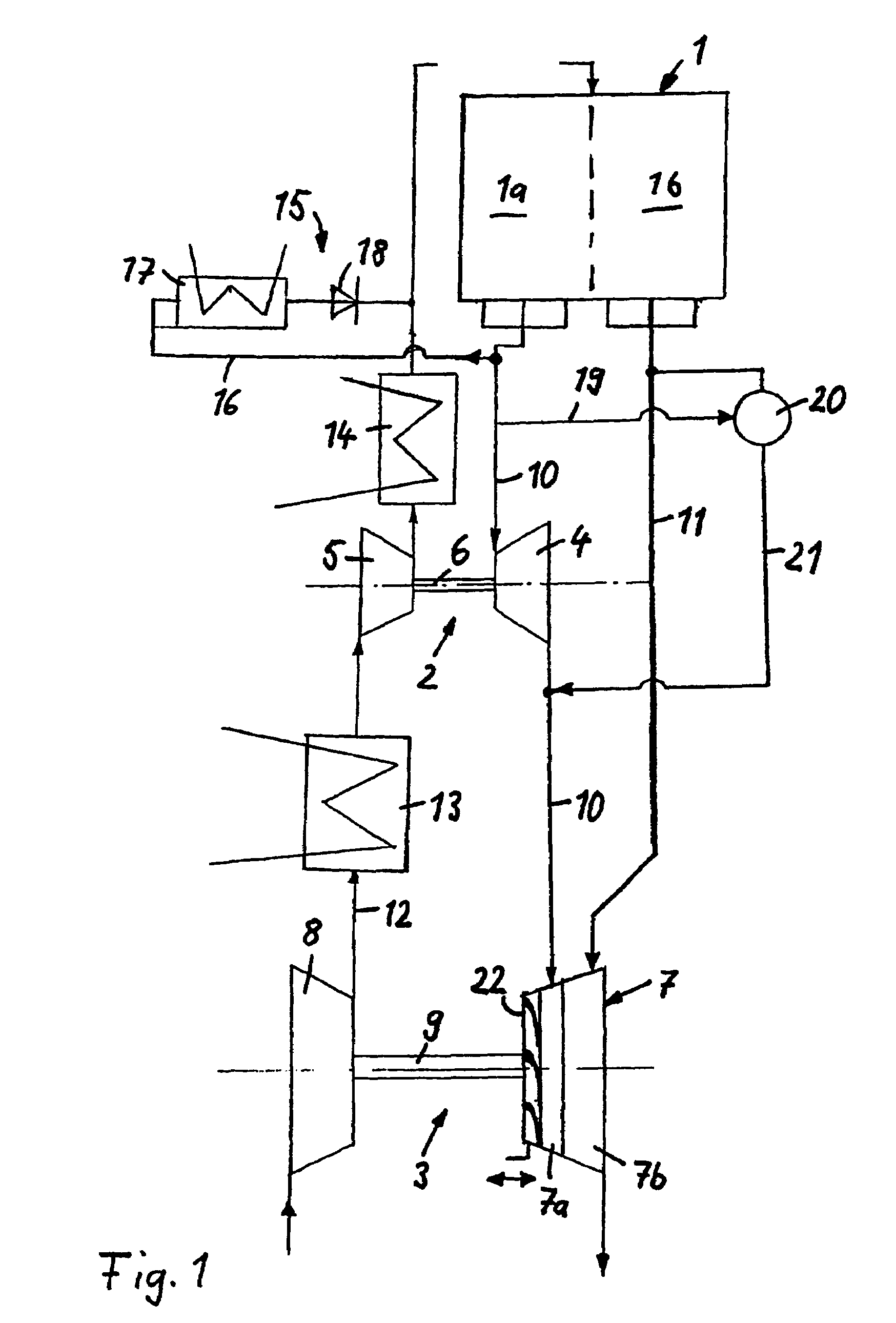
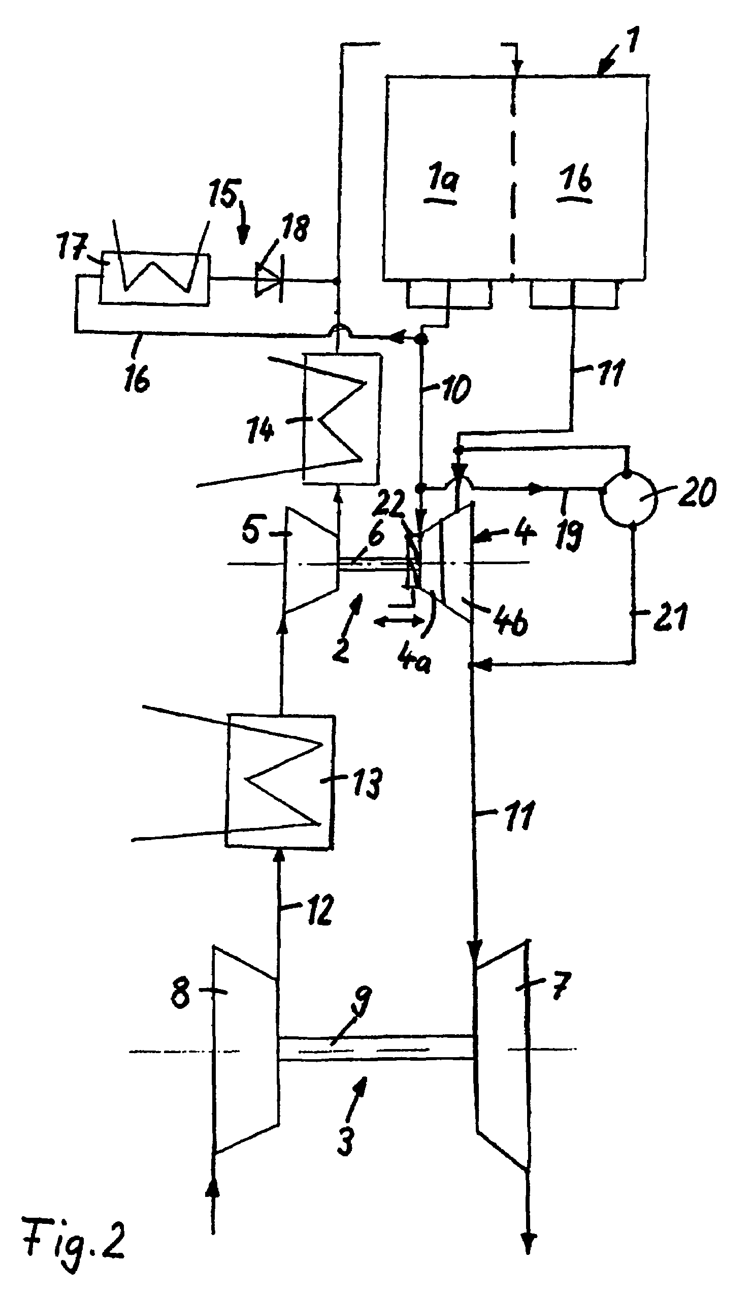
[0023]The internal combustion engines illustrated in FIGS. 1 and 2 are a spark ignition engine or a diesel engine.

[0024]The internal combustion engine 1 illustrated in FIG. 1, has two cylinder banks 1a and 1b, and two exhaust gas turbochargers 2 and 3 connected in series. The first exhaust gas turbocharger 2 is arranged near the engine, and carries out the function of a high pressure supercharger, and the second exhaust gas turbocharger 3 is remote from the engine and carries out the function of a low pressure supercharger. The high pressure supercharger is smaller than the low pressure supercharger and for this reason also has a lower moment of mass inertia. The exhaust gas turbocharger 2 which is near the engine comprises an exhaust gas turbine 4 in the exhaust gas section of the internal combustion engine whose turbine wheel is connected via a shaft 6 to the compressor wheel in the compressor 5 which is located in the intake section 12 of the internal combustion engine. In a corr...


PUM


Abstract

In an internal combustion engine provided with two exhaust gas turbochargers which each comprise a turbine in an exhaust line and one compressor in an intake section of the engine, two exhaust lines are provided which are each assigned to at least one of the exhaust gas turbines, an exhaust gas recirculation device being arranged between an exhaust line upstream of an exhaust gas turbine and the intake section downstream of a compressor and the two exhaust lines including bypass lines with a control valve for selectively permitting the exhaust gas to bypass the turbine closer to the engine.

Description

[0001]This is a Continuation-In-Part Application of International Application PCT / EP2005 / 001908 filed Feb. 04, 2005 and claiming the priority of German Application 102004009794.1 filed Feb. 02, 2004.BACKGROUND OF THE INVENTION[0002]The invention relates to an internal combustion engine having two exhaust gas turbochargers, each including a turbine and a compressor, disposed in series circuits and an exhaust gas recirculation line including a non-return valve connected to an exhaust duct upstream of an exhaust gas turbine for returning exhaust gas to a compressor air intake duct.[0003]DE 101 44 663 A1 discloses an internal combustion engine having two exhaust gas turbochargers, a first turbocharger forming a high pressure stage, and the second turbocharger forming a low pressure stage. The high pressure stage is arranged near to the engine, and the low pressure stage is in contrast located at a relatively large distance from the internal combustion engine. The compressors of the two ...

Claims


Application Information

Patent Timeline
Patent Type & Authority Patents(United States)
IPC IPC(8): F02B37/00F02B37/013F02B37/18F02M25/07F02B37/007
CPCF02B37/18F02M25/0711F02B29/0412F02B37/001F02B37/004F02B37/013F02B37/025F02M25/0727F02M25/0749Y02T10/121Y02T10/146Y02T10/144F02M26/08F02M26/23F02M26/43Y02T10/12
Inventor SCHMID, WOLFRAMSUMSER, SIEGFRIED
Owner DAIMLER AG
Why Eureka
Try Eureka