
Microcontroller, switched-mode power supply, ballast for operating at least one electric lamp, and method of operating at least one electric lamp

a microcontroller and switched-mode power supply technology, applied in the direction of instruments, light sources, lighting apparatus, etc., can solve the problems of inability to carry out finely graduated pulse-width modulation control nor any finely graduated frequency control of the inverter, and the frequency of the control signal which can be generated by the counting mechanism explained above, etc., to achieve the effect of saving components

Inactive Publication Date: 2004-04-06
PATENT TREUHAND GESELLSCHAFT FUR ELECTRIC GLUEHLAMPEN MBH
View PDF9 Cites 39 Cited by
  • Summary
  • Abstract
  • Description
  • Claims
  • Application Information

AI Technical Summary

Benefits of technology

"The invention is a microcontroller with improved control over the pulse-width modulation and frequency control of a switched-mode power supply. It includes a device for alternate charging and discharging of a charge store, which allows for controlled charging and discharging operations independently. The device for alternate charging and discharging of a charge store has controllable current source and current sink for applying adjustable charging and discharging currents, and a controllable current store for storing energy. The microcontroller also has a frequency divider or pulse divider to evaluate the charge state of the charge store and generate frequency control signals and pulse-width modulation control signals for the switched-mode power supply. The microcontroller can also have interfaces for registering external signals or data and program-controlled determination of actuating values for controlling the device for alternate charging and discharging of a charge store. The switched-mode power supply according to the invention has improved control over the pulse-width modulation and frequency control of the switching transistors, resulting in better performance and efficiency."

Problems solved by technology

However, in this way, using cost-effective microcontrollers, no finely graduated pulse-width modulation control nor any finely graduated frequency control of the inverter can be carried out, since the smallest possible, adjustable change in the pulse width or in the frequency of the control signal which can be generated by the counting mechanism explained above is limited by the operating cycle frequency of the microcontroller and by the memory size of the counting mechanism.
However, for cost reasons, such microcontrollers cannot be used in electronic ballasts for lamp operation.

Method used


Image

  • Microcontroller, switched-mode power supply, ballast for operating at least one electric lamp, and method of operating at least one electric lamp
  • Microcontroller, switched-mode power supply, ballast for operating at least one electric lamp, and method of operating at least one electric lamp
  • Microcontroller, switched-mode power supply, ballast for operating at least one electric lamp, and method of operating at least one electric lamp

Examples


Embodiment Construction

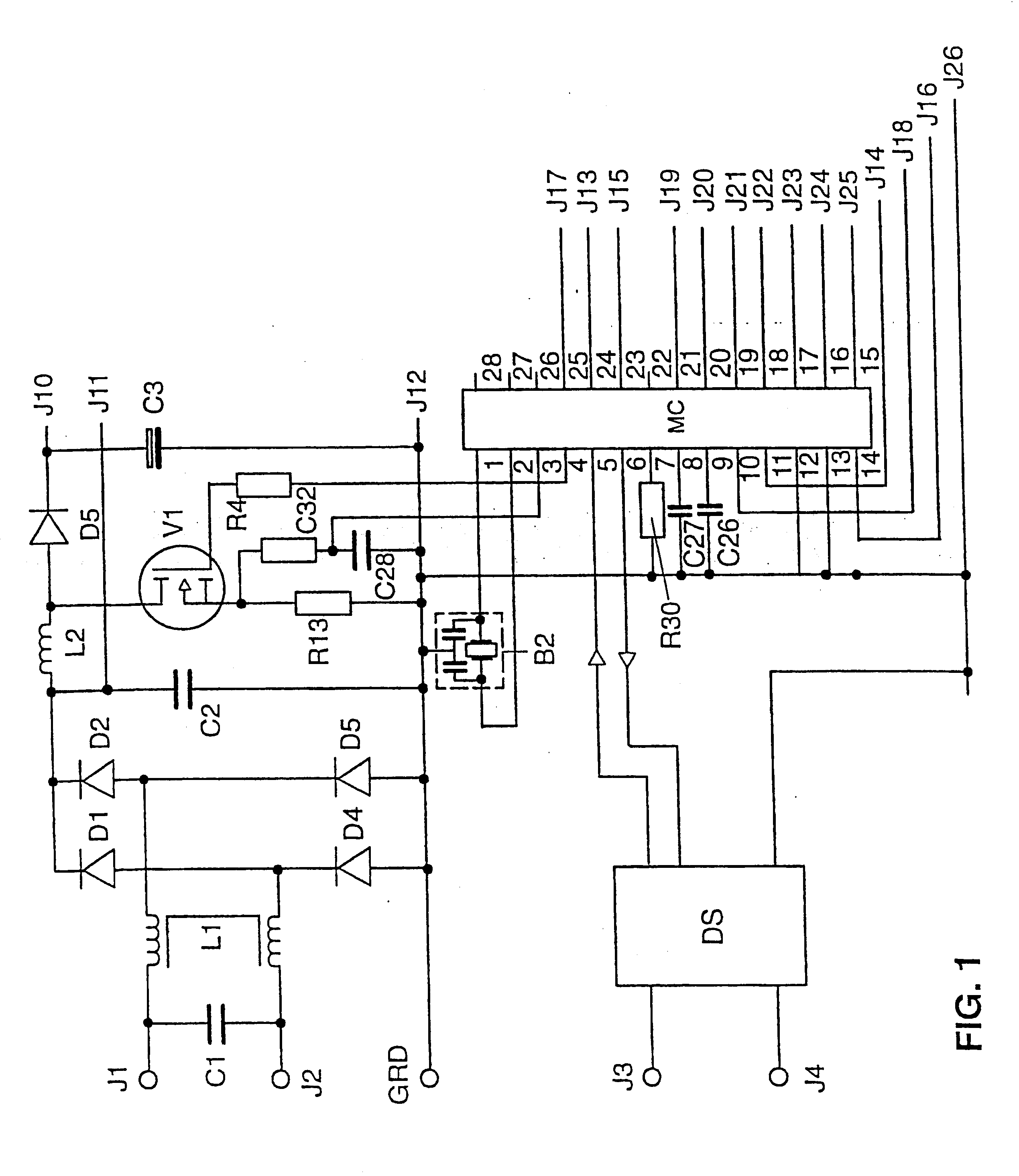
The circuit arrangement of the preferred exemplary embodiment of the ballast according to the invention is illustrated schematically in FIGS. 1 and 2. Because of its size, the circuit arrangement has had to be illustrated on two sheets. The two halves of the circuit arrangement, depicted in FIGS. 1 and 2, are linked to each other at the connecting points designated by J10 to J26. This ballast is an electronic ballast, as it is known, for operating fluorescent lamps. The ballast has two mains voltage terminals J1, J2, to which a filter circuit, comprising the capacitor C1 and the transformer L1, is connected to suppress radio interference from the ballast. This filter circuit is connected to a bridge rectifier, which is formed by four rectifier diodes D1, D2, D3 and D4. Connected downstream of the bridge rectifier D1-D4 is the capacitor C2, which forms the DC output of the bridge rectifier D1-D4. Connected to the capacitor C2 is a step-up converter, which comprises the field effect t...


PUM


Abstract

The invention relates to a microcontroller (MC) having at least one device (G) for generating pulse-width modulated or frequency modulated control signals for a switched-mode power supply. The device (G) has a further device (SQ1, SS1) for the alternate charging and discharging an electric charge store (C27) that can be connected to the microcontroller (MC), control means for this device (SQ1, SS1) for controlling the charging and discharging operations, and an evalutor for evaluating the time periods which are needed for the individual charging and discharging operations to generate pulse-width modulated or frequency modulated control signals. The microcontroller (MC) generates finely graduated, frequency modulated or pulse-width modulated control signals which are independent of the operating cycle frequency of the microcontroller (MC).

Description

The invention relates to a microcontroller according to the preamble of patent claim 1, a switched-mode power supply according to patent claim 10, a ballast for at least one electric lamp according to the preamble of patent claim 11, and a method of operating at least one electric lamp according to the preamble of patent claim 25.I. TECHNICAL FIELDIn particular, the invention relates to a microcontroller which is provided to drive the switching transistors of a switched-mode power supply, to be specific preferably of a switched-mode power supply for operating electric lamps. In the switched-mode power supplies normally used to operate electric lamps, there are normally inverters, in particular half-bridge, full-bridge and push-pull inverters, and also step-up converters and step-down converters. Modern electronic ballasts for operating electric lamps generally have an inverter to produce a high-frequency alternating current for lamp operation and often also have a step-up converter ...

Claims


Application Information

Patent Timeline
Patent Type & Authority Patents(United States)
IPC IPC(8): H05B41/39H05B41/392
CPCH05B41/3921
Inventor KRUMMEL, PETER
Owner PATENT TREUHAND GESELLSCHAFT FUR ELECTRIC GLUEHLAMPEN MBH
Learn More