Organic light emitting display device and driving method thereof

a light-emitting display device and organic technology, applied in the direction of lighting devices, light sources, instruments, etc., can solve the problems of unsatisfactory electrical components of transistors within the pixel circuit, the voltage level of the signals generated by the scan driver may not reach the threshold, and the scan driver may not work properly, so as to improve the driving effect and improve the quality of images displayed

Inactive Publication Date: 2008-10-09
SAMSUNG DISPLAY CO LTD
View PDF9 Cites 54 Cited by
  • Summary
  • Abstract
  • Description
  • Claims
  • Application Information

AI Technical Summary

Benefits of technology

[0017]It is, therefore, an object of the present invention to provide an improved organic light emitting display device and an improved driving method thereof to provide better quality of images displayed on the displays.

Problems solved by technology

Recently, various flat panel display devices with lighter weight and less volume, because heavier weight and more volume are considered as disadvantages of a cathode ray tube.
Therefore, the prior art may cause a malfunction of the scan driver, for example, the voltage level of the signals generated from the scan driver may not reach the threshold capable of driving a pixel.
The transistors within the pixel circuit, however, are not ideal electrical components completely blocking leak current flows between terminals thereof, and floating state is established in the standby state where the first and second pixel power supplies are applied.
Therefore, abnormal current is applied to the organic light emitting diode in the standby state, and it may cause problems of displaying images in an undesired shape or abnormally lighting the pixels such as blinking.

Method used


Image

  • Organic light emitting display device and driving method thereof
  • Organic light emitting display device and driving method thereof
  • Organic light emitting display device and driving method thereof

Examples


Embodiment Construction

[0031]Hereinafter, preferable embodiments according to the present invention, which can be easily carried out by those skilled in the art, will be described with reference to the accompanying FIG. 1 to FIG. 6.

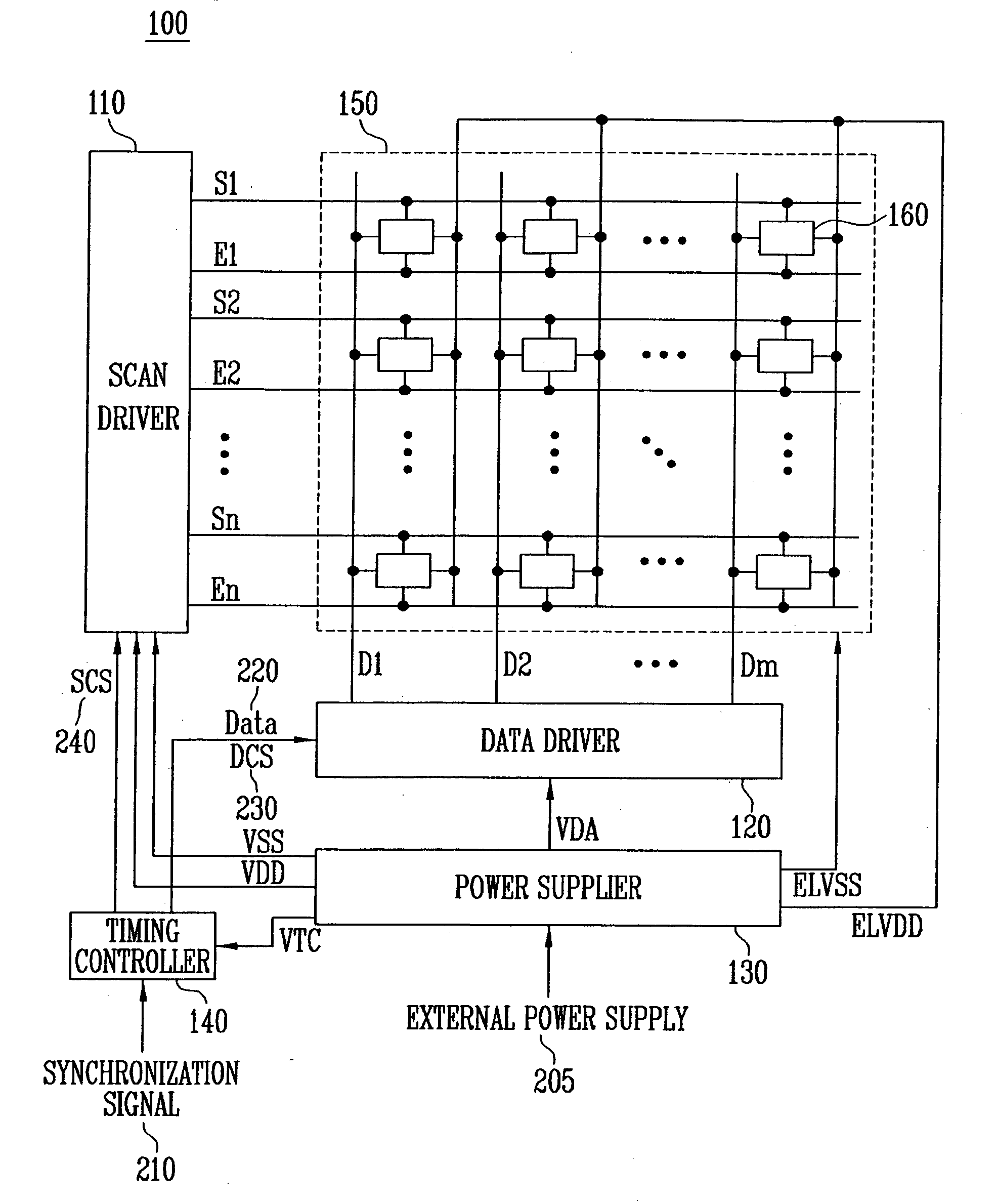
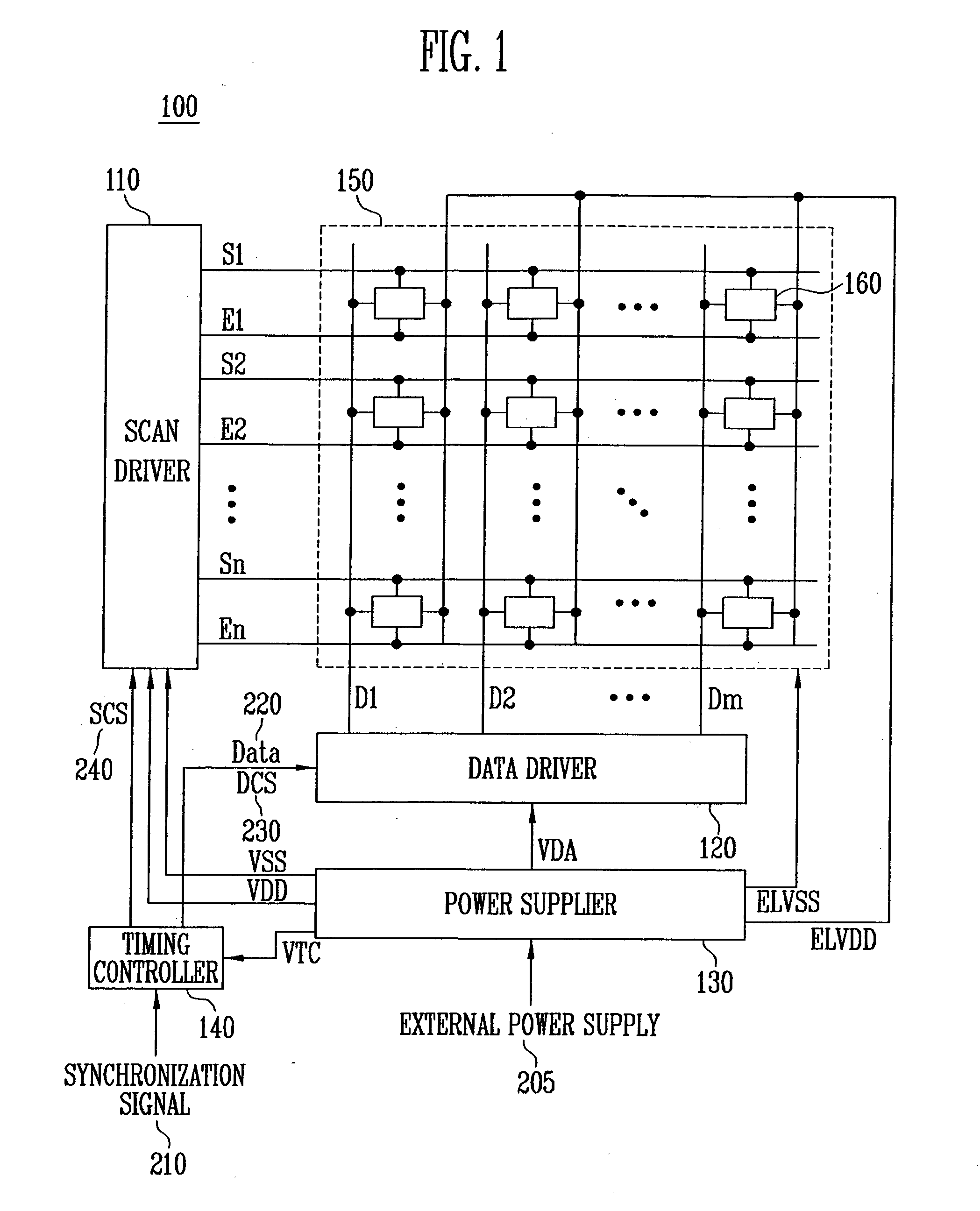
[0032]FIG. 1 is an illustrate of an organic light emitting display device constructed according to one embodiment of the present invention.

[0033]Referring to FIG. 1, an organic light emitting display device 100 according to an embodiment of the present invention includes a scan driver 110, a data driver 120, a timing controller 140, a pixel unit 150 and a power supplier 130.

[0034]Scan driver 110 generates scan signals and light emitting control signals corresponding to scan driving control signals SCS 240 supplied from the timing controller 140. The scan signals and light emitting control signals generated by scan driver 110 are sequentially supplied to scan lines S1 to Sn and light emitting control lines E1 to En, respectively. Scan driving control signals SCS 240 include star...


PUM


Abstract

An organic light emitting display device and a driving method thereof, capable of preventing malfunction due to an overload of a scan driver and an abnormal lighting phenomenon of pixels.
A driving method of an organic light emitting display device according to the present invention includes the steps of: supplying scan signals generated by scan driving power supplies and scan driving control signals to a pixel unit; supplying data signals generated by data driving power supplies, data, and data driving control signals to the pixel unit; and light emitting pixels provided in the pixel unit by means of pixel power supplies supplied to the pixel unit after the scan signals and the data signals are generated, the scan signals and data signals. The organic light emitting display device has a timing controller supplying output enable signals to the scan driver one or more frames after the time point of starting supplying start pulses and clock signals to the scan driver and a power supplier supplying pixel power supplies after the generation of scan signals and data signals starts.

Description

CLAIM OF PRIORITY[0001]This application makes reference to, incorporates the same herein, and claims all benefits accruing under 35 U.S.C. §119 from an application for ORGANIC LIGHT EMITTING DISPLAY AND DRIVING METHOD THEREOF earlier filed in the Korean Intellectual Property Office on 6th of April 2007 and there duly assigned Serial No. 10-2007-0034098.BACKGROUND OF THE INVENTION[0002]1. Field of the Invention[0003]The present invention relates to an organic light emitting display device and a driving method thereof, and more particularly to an organic light emitting display device and a driving method thereof capable of preventing malfunction due to an overload of a scan driver and an abnormal lighting phenomenon of pixels.[0004]2. Description of the Related Art[0005]Recently, various flat panel display devices with lighter weight and less volume, because heavier weight and more volume are considered as disadvantages of a cathode ray tube. Flat panel display devices have many kinds...

Claims


Application Information

Patent Timeline
Patent Type & Authority Applications(United States)
IPC IPC(8): G09G3/30
CPCG09G3/3225G09G3/3266G09G2300/0861G09G2310/06G09G2330/025G09G2330/04G09G3/20G09G3/30G09G3/32H05B33/12
Inventor EOM, KI-MYEONG
Owner SAMSUNG DISPLAY CO LTD
Why Eureka
Try Eureka