Bi-stable electrostatic comb drive with automatic braking

a comb drive, automatic braking technology, applied in the direction of electrostatic motors, electrostatic generators/motors, electrical apparatus, etc., can solve the problems of mechanical overshoot and ringing, complicated device packaging, and most compliant comb drives to overshoot the desired position. , to achieve the effect of high motive for

Inactive Publication Date: 2002-09-19
LUMENTUM OPERATIONS LLC
View PDF0 Cites 56 Cited by
  • Summary
  • Abstract
  • Description
  • Claims
  • Application Information

AI Technical Summary

Benefits of technology

0015] In another embodiment the movable portion of the comb drive has opposing sets of fingers, each set interdigitated with a corresponding set of fixed fingers. The reciprocal nature of the device, namely that a simple, square-wave pulse of the same polarity will toggle the drive, in combination with the latching spring arms provides a compact and efficient MEMS actuator with relatively high motive force.

Problems solved by technology

However, mechanical overshoot and ringing can occur due to the kinematics of the comb drive.
For example, an actuating pulse of sufficient voltage and duration to switch the least compliant comb drive may cause the most compliant comb drive to overshoot the desired position due to the momentum of the movable elements.
Such overshoot can cause a number of problems.
For example, the momentum might cause the generally thin, fragile interdigitated fingers to crash into the opposite wall of the comb drive, or the movable element might first overshoot and then recoil back to the original position.
This settling can require an additional period to be specified in the switching time of the device, which is generally undesirable.
Some devices use a fluid, such as a heavy gas, pressurized gas, or liquid, to damp the ringing more quickly; however these fluids complicate packaging of the device and may be unwanted or even prohibited in some commercial applications because of the change in performance or damage to other devices if the fluid leaks out.
In a latching electrostatic comb drive system, overshoot of the movable portion of the device might even cause the movable portion, after overshooting the desired position, to spring back to latch in the initial position.

Method used


Image

  • Bi-stable electrostatic comb drive with automatic braking
  • Bi-stable electrostatic comb drive with automatic braking
  • Bi-stable electrostatic comb drive with automatic braking

Examples


Embodiment Construction

[0042] I. Introduction

[0043] The present invention provides a compact, efficient, and predictable electrostatic comb drive that is easily reset to a default position and can be latched in either of two switch positions. The latching is achieved using mechanical means and hence the state of the switch can be maintained without the continuous application of electrical power or voltage. Efficiency is achieved with bi-directional pulling from either state with shaped comb fingers. The drive may be reset to a known state by applying an electric voltage between the movable and fixed fingers of the comb drive to hold the drive in the position of minimum electric potential, and then removing the voltage to release the comb drive to a default position.

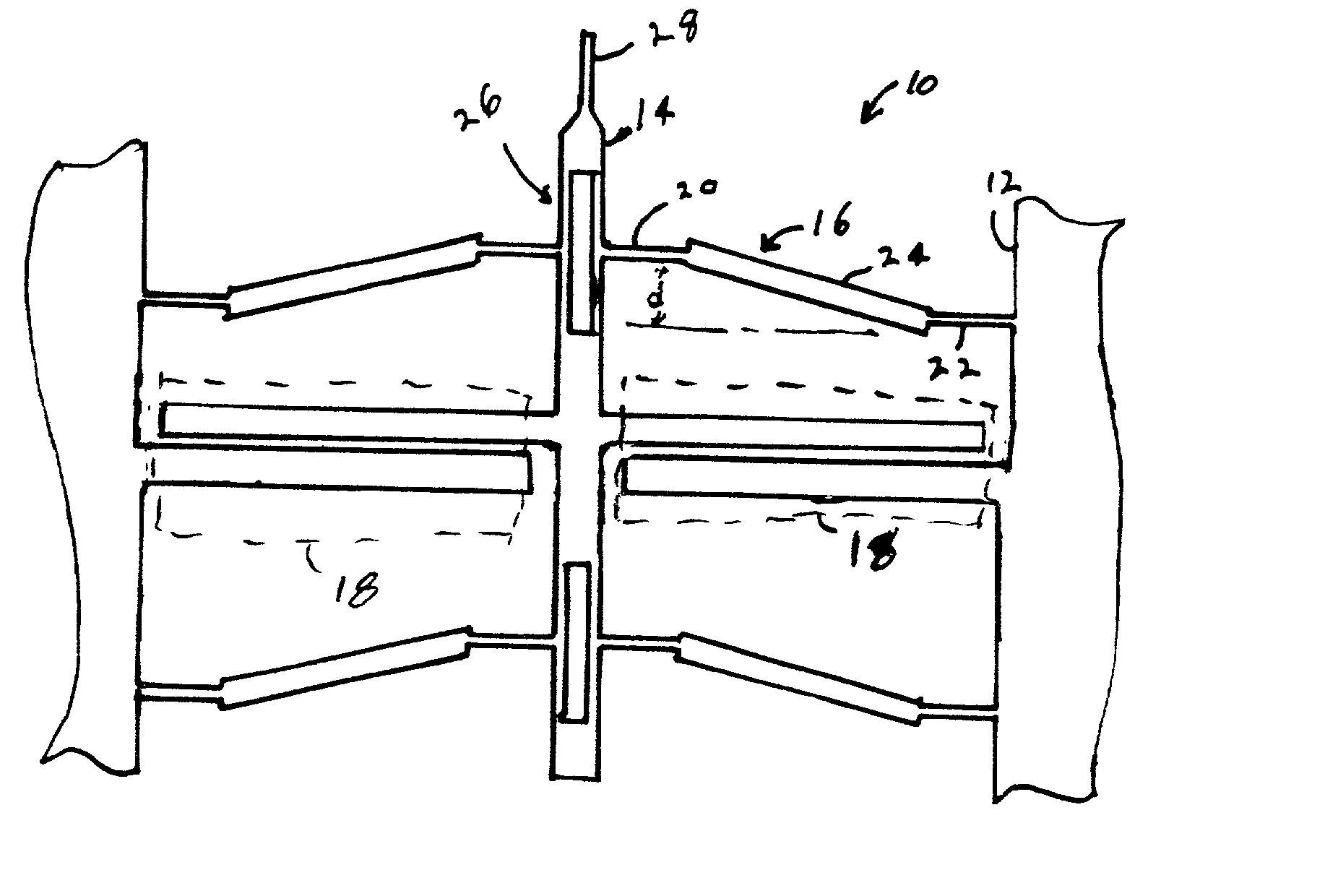
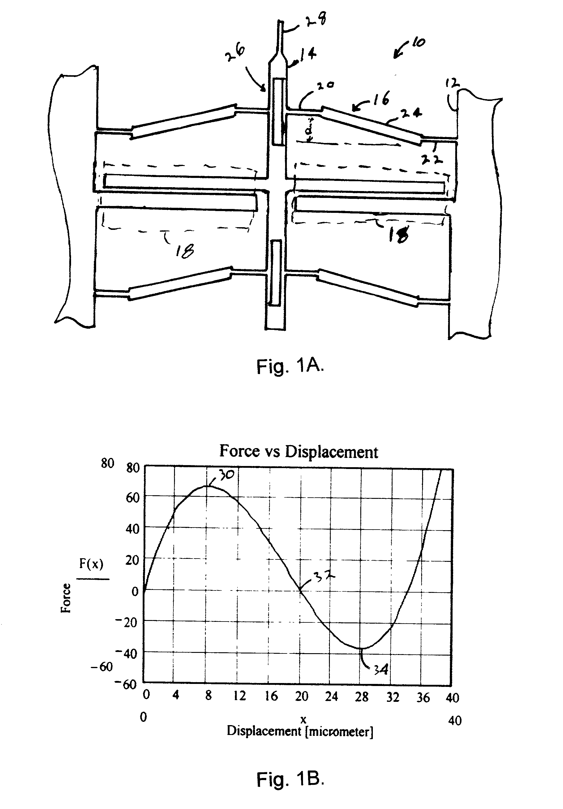
[0044] 2. Exemplary MEMS Devices

[0045] FIG. 1A is a simplified top view of a MEMS device with an exemplary mechanical latching spring system. The MEMS device has a base 12 or body and a movable element 14 attached to the base with latching spri...


PUM


Abstract

An electrostatic comb drive suitable for micro-electro-mechanical systems ("MEMS") application uses shaped fingers to achieve bi-directional actuation from a uni-polar actuation pulse. The finger shape also provides auto-braking of the movable member of the drive using a simple actuating pulse. In a further embodiment, an end stop inhibits overshoot and a back spring pushes the movable portion of the device back toward an operating position. In yet a further embodiment, a Vernier scale is provided on the movable portion of the drive relative to the fixed portion of the drive to indicate relative shift of these portions after the device is fabricated.

Description

CROSS-REFERENCE TO RELATED APPLICATIONS[0001] Not applicable.STATEMENT REGARDING FEDERALLY SPONSORED RESEARCH OR DEVELOPMENT[0002] Not applicable.REFERENCE TO MICROFICHE APPENDIX[0003] Not applicable.BACKGROUND OF THE INVENTION[0004] The invention relates generally to motors or drives for micro-electro-mechanical systems (MEMS) devices, and more particularly to inter-digitated electrostatic comb drives.[0005] A variety of drives and motors have been developed for MEMS applications to actuate a variety of devices, such as electronic or fluid switches, or to move an object, such as a mirror or other optical device, from one position to another. For example, MEMS devices have been developed for use in optical switching applications in optical communication systems.[0006] One such device uses a small mirror fabricated on a movable portion of a MEMS drive, the mirror being moved into and out of the path of an optical beam. When the mirror is out of the beam path, the optical beam continu...

Claims


Application Information

Patent Timeline
Patent Type & Authority Applications(United States)
IPC IPC(8): H02N1/00
CPCH02N1/008
Inventor MAO, MINYAOFRIEDRICH, DONALD M.DUELLI, MARKUSHICHWA, BRYANT
Owner LUMENTUM OPERATIONS LLC
Why Eureka
Try Eureka