Submersible electric pump

a technology of electric pump and submerged well, which is applied in the direction of piston pump, positive displacement liquid engine, borehole/well accessories, etc., can solve the problems of insufficient formation pressure to drive fluid upward in the wellbore, many hydrocarbon wells are unable to produce at commercially viable levels, and certain difficulties in connection with the use of sucker rods

Inactive Publication Date: 2005-08-09
SHELL INT EXPLORATION & PRODN +2
View PDF24 Cites 57 Cited by
  • Summary
  • Abstract
  • Description
  • Claims
  • Application Information

AI Technical Summary

Benefits of technology

[0027]A method of completing a wellbore or otherwise pumping fluids using a plurality of electrical pumps is also provided. The pumps are in series with the tubing and are set at selected depths. Pump designs are provided herein which allow for either rotary motors or linear motors to be used in the wellbore. A series of submersible electrical pumps may be provided ...

Problems solved by technology

Many hydrocarbon wells are unable to produce at commercially viable levels without assistance in lifting formation fluids to the earth's surface.
More commonly, formation pressure is inadequate to drive fluids upward in the wellbore.
Certain difficulties are experienced in connection with the use of sucker rods.
The primary problem is rooted in the fact that most wells are not truly straight, but tend to deviate in various directions en route to the zone of production.
Deviations in the direction of a downhole well cause friction to occur between the sucker rod joints and the production tubing.
This, in turn, causes wear on the sucker rod and the tubing, necessitating the costly replacement of both.
Further, the friction between the sucker rod and the tubing wastes energy and requires the use of higher capacity motors at the surface.
Submersible pump assemblies which utilize a linear electric motor have not been introduced to the oil field in commercially significant quantities.
Such pumps would suffer from several challenges, if employed.
A first problem relates to the introduction of the submersible pump into the wellbore.
At the same time, submersible pumps can be of such a length that it becomes difficult for the pump to negotiate turns and bends within the tubing string of the well.
Overriding this concern is the expense of manufacturing and stocking submersible pumps of various sizes.
Another problem relates to the inconsistent power sources at wellsites.
Power surges associated with the start of the motor create harmful temperature variations and mechanical stresses which cause wear of the electrical insulators, connections and coils.
Further, power sources themselves provide inconsistent electricity flow.
Power spikes, interruptions in services, and other causes of uneven power supply generate, by the Joule effect, temperature variat...

Method used


Image

  • Submersible electric pump
  • Submersible electric pump
  • Submersible electric pump

Examples


Embodiment Construction

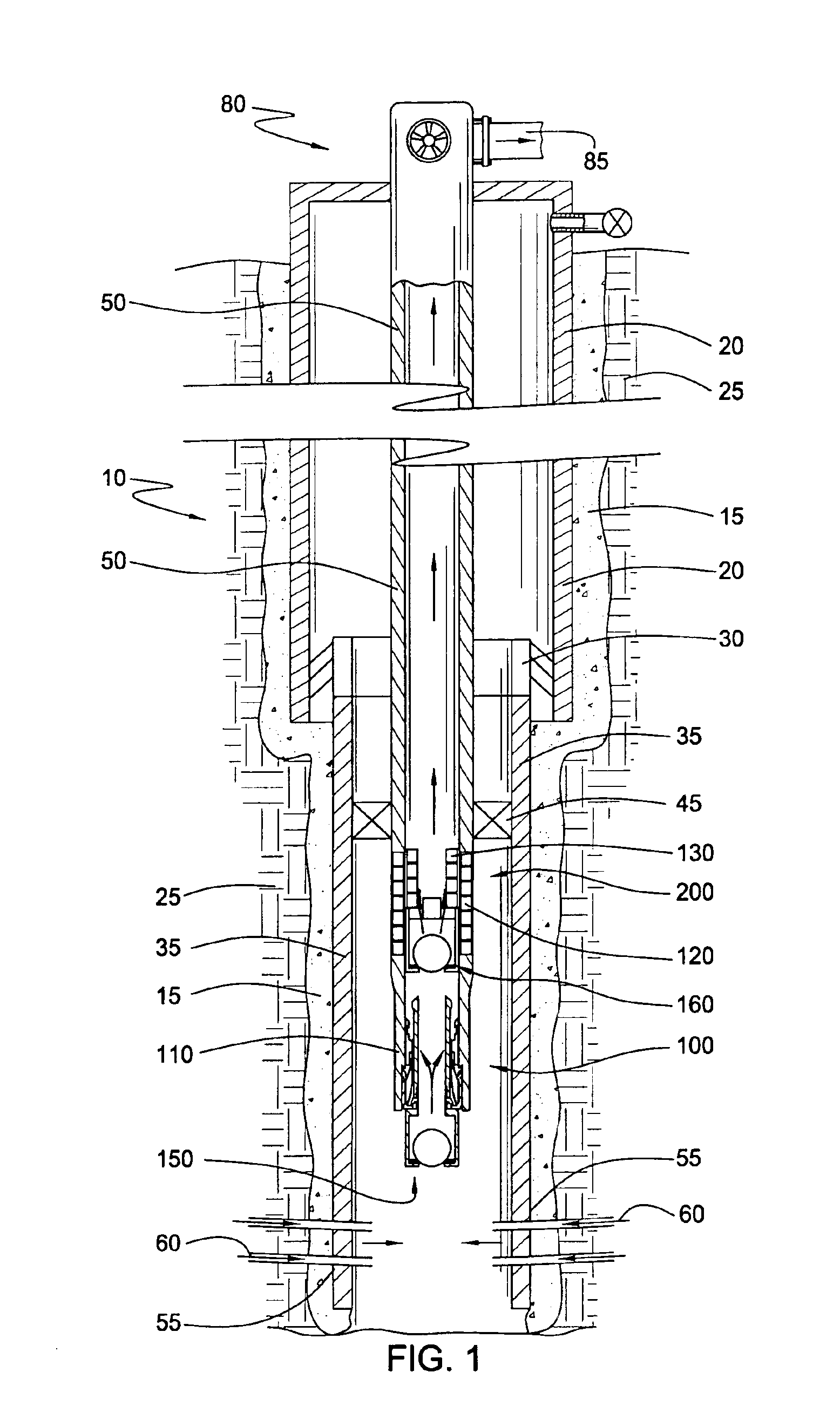
[0038]FIG. 1 presents a cross-sectional view of a wellbore 10. As completed in FIG. 1, the wellbore 10 has a first string of surface casing 20 hung from the surface. The first string 20 is fixed in a formation 25 by cured cement 15. A second string of casing 35 is also visible in FIG. 1. The second casing string 35, sometimes referred to as a “liner,” is hung from the surface casing 20 by a conventional liner hanger 30. The liner hanger 30 employs slips which engage the inner surface of the surface casing 20 to form a frictional connection. The liner 35 is also cemented into the wellbore 10 after being hung from the surface casing 20.

[0039]The wellbore 10 is shown in a state of production. First, the liner 35 has been perforated in order to provide fluid communication between the wellbore 10 and a producing zone in the formation 25. Perforations may be seen at 55. Arrows 60 depict the flow of hydrocarbons into the wellbore 10. Second, a string of production tubing 50 is shown. The p...


PUM


Abstract

An improved electrical pump is first provided for use in a wellbore. The pump comprises a stator and a stator housing, and an armature and an armature housing. The stator housing and the armature housing define concentrically nested tubular bodies. The armature housing is configured to permit production fluids to flow therethrough. In one aspect, the stator and armature are assembled in connectible and interchangeable sections called “modules” that can be attached in series. In one aspect, the electrical operation of coils within the stator is protected from individual coil short-circuiting or failure by wiring them in parallel, rather than in series. In addition, each module may be wired in parallel. In this way, a failure of one stator module will not result in the failure of another stator module. In an embodiment of the present invention, the valves of the pump are capable of being retrieved by a wireline, without pulling the entire production string. A method for using a plurality of electrical pumps is also provided. The configuration of the electrical pumps allows multiple linear pumps to be placed in series with the production tubular member. Alternatively, a rotary pump design is provided which allows multiple rotary pumps to be placed in series with the production tubular member.

Description

CROSS-REFERENCE TO RELATED APPLICATIONS[0001]This application claims priority to a pending provisional patent application entitled “Submersible Electrical Pump, and Method for Using Plurality of Submersible Electrical Pumps for Well Completion.” That provisional application was filed on Jun. 26, 2001, and was assigned Ser. No. Prov. 60 / 301,332.BACKGROUND OF THE INVENTION[0002]1. Field of the Invention[0003]This invention relates to pumping apparatus for transporting fluids from a well formation to the earth's surface. More particularly, embodiments of the invention pertain to an improved electrical pump comprising a downhole linear electric motor and a positive displacement pump assembly. In addition, embodiments of the invention relate to the use of a plurality of submersible electrical pumps in the completion or operation of a well.[0004]2. Description of the Related Art[0005]Many hydrocarbon wells are unable to produce at commercially viable levels without assistance in lifting f...

Claims


Application Information

Patent Timeline
IPC IPC(8): E21B27/00E21B27/02E21B43/12
CPCE21B27/02E21B43/128F04B47/02
Inventor HOWARD, WILLIAM F.
Owner SHELL INT EXPLORATION & PRODN
Why Eureka
Try Eureka