Powered auxiliary hoist mechanism for a gantry crane

a technology of gantry crane and hoist mechanism, which is applied in the direction of cranes, load-engaging elements, trolleys, etc., can solve the problems of nevertheless having certain limitations, and achieve the effect of reducing the second weight capacity and efficiently storing the panels

Active Publication Date: 2009-06-16
MARINE TRAVEELEVATOR
View PDF53 Cites 44 Cited by
  • Summary
  • Abstract
  • Description
  • Claims
  • Application Information

AI Technical Summary

Benefits of technology

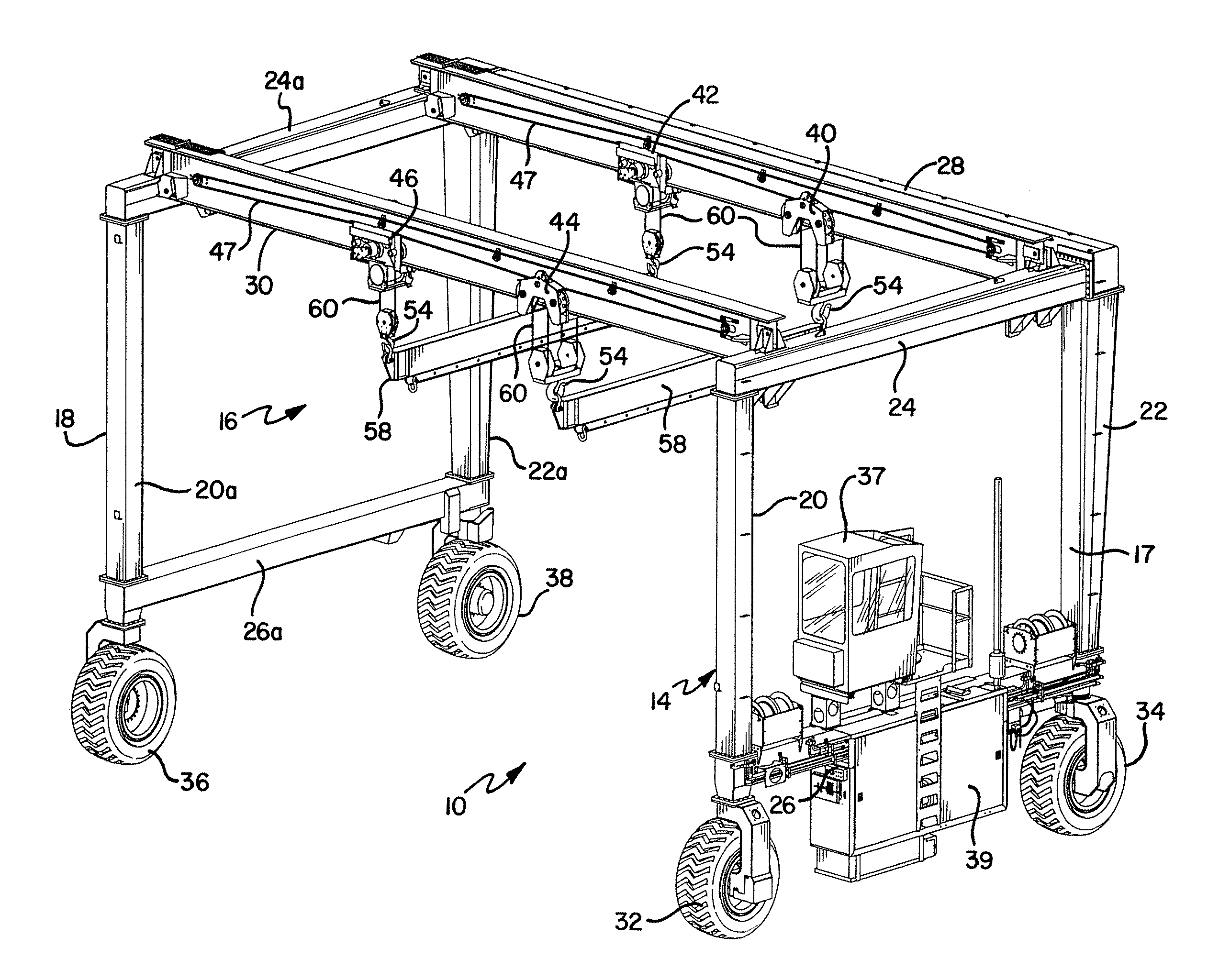
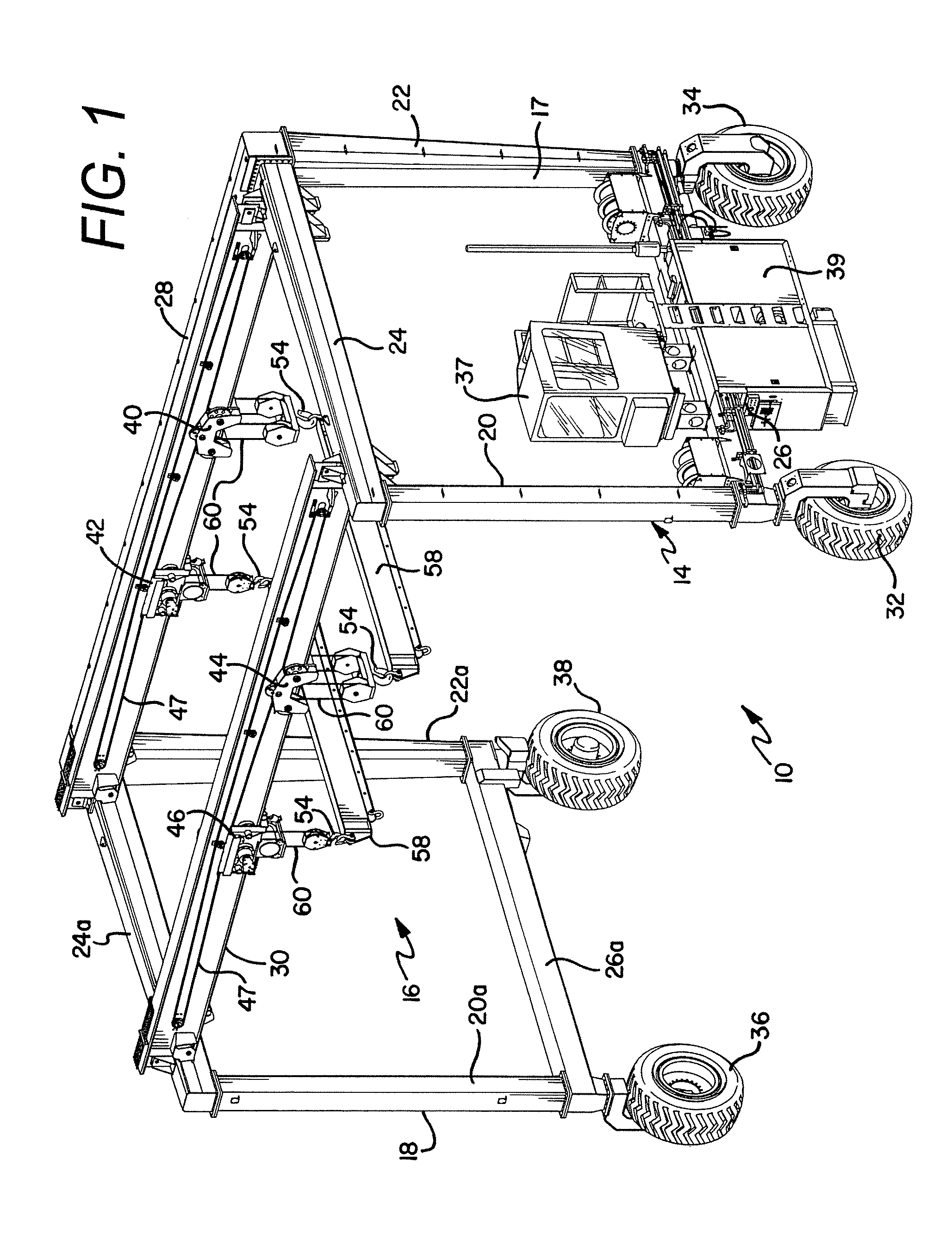
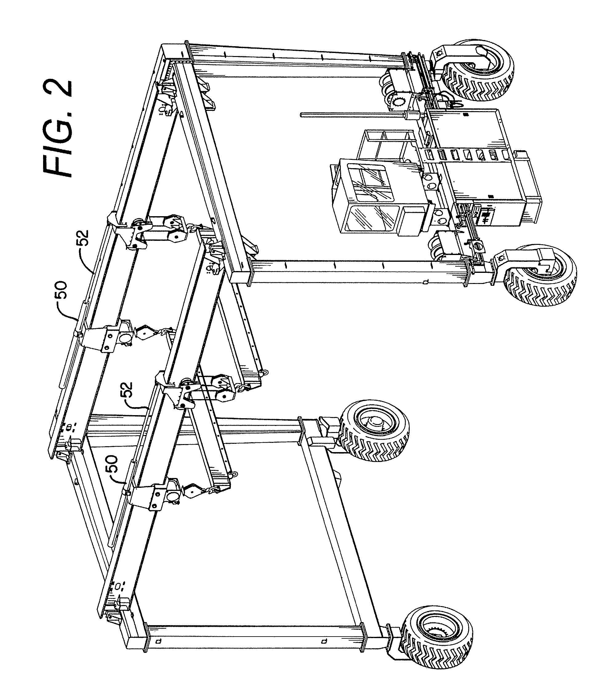
[0009]According to one aspect of the invention, a gantry crane has a gantry structure including a first horizontal beam and a second horizontal beam, and lift mechanisms secured to the horizontal beams. The lift mechanisms can include hoist mechanisms (sometimes referred to simply as “hoists”) and trolley assemblies for lateral movement on the horizontal beams. Typically, the gantry crane will include a main hoist trolley and an auxiliary hoist trolley on each beam which are controlled by a hydraulic system. The hydraulic system of the present invention is configured to reduce the hoist capacity (i.e., the lifting capacity) of the main hoist trolleys to protect the overhead horizontal beams from being overloaded. This is done when it is necessary to use both the main hoist and the auxiliary hoist to lift a load.
[0012]In situations that require use of the main hoist trolley and the auxiliary hoist trolley, the hydraulic system of the gantry crane of the present invention is configured to reduce the main hoist capacity to a lesser amount. Preferably, the main hoist trolley is limited to 13 tons (or less) so that with the auxiliary hoist trolley rated at 12 tons, a total lifting capacity of each set of main and auxiliary hoist trolleys will be 25 tons (or less). This will then match (or be lower than) the 25 ton rating of the horizontal beam. In this manner, any attempt made to lift a greater weight will be prevented. Instead, the lifting mechanisms will de-rate, thereby avoiding significant damage to the beams or other portions of the crane's support structure.
[0013]The system uses a load sense diverter valve and load sense pressure limiting valve in the hydraulic circuit controlling the main hoist directional control valve to accomplish the hoist capacity reduction. Thus, if a hoist selection is made which utilizes both the main and auxiliary hoists for one of the beams, or all four of the hoists are selected by the operator, the hoist command signal from the operator causes the load sense pressure signal from the main hoist directional valve to be diverted through the pressure limiting valve to reduce the main hoist trolley lifting capacity (when all four hoist are selected for use this reduction in capacity is done on both main hoists). This protects the crane from overloading the overhead horizontal beams.
[0014]According to another aspect of the invention, the panel turner system provides for equalizing the hoisting capacity of the auxiliary hoists in certain applications. If more than one auxiliary hoist joystick is actuated, the system utilizes a common hydraulic line to hydraulically equalize the auxiliary hoists. This will assure that the auxiliary hoists carry equal portions of the lifted load (e.g., when lifting or lowering the load). This feature helps to prevent unequal load distribution between the auxiliary hoists which could otherwise result in damage to the lifted load and / or the gantry crane.
[0015]According to yet another aspect of the invention, a load lifting assembly is provided comprising a load lifting support structure having a first horizontal beam with a first main hoist mechanism and a first auxiliary hoist mechanism coupled to the first horizontal beam. A hydraulic circuit is configured to operate the first hoist mechanism coupled to the first horizontal beam. A first load sense pressure limiting valve is incorporated in the hydraulic circuit and is configured to reduce the lift capacity of the first hoist mechanism coupled to the first horizontal beam when both the first main hoist mechanism and the first auxiliary hoist mechanism are utilized to lift the load. Specifically, a diverter valve incorporated in the first hydraulic circuit is configured to divert a hydraulic control line from a main hoist directional control valve in the hydraulic circuit through the pressure limiting valve to the pressure compensated load sense pump when both the first main hoist mechanism and the first auxiliary hoist mechanism are utilized to lift a load. In this manner, the pressure limiting valve is able to control or adjust the pressure in a hydraulic pressure line from the pressure compensated load sense pump to the main hoist directional control valve.
[0023]This method can be employed in a panel turner application and can include lifting a panel with the first main hoist mechanism, the first auxiliary hoist mechanism, the second main hoist mechanism and the second auxiliary hoist mechanism and, turning the panel with the first main hoist mechanism, the first auxiliary hoist mechanism, the second main hoist mechanism and the second auxiliary hoist mechanism. The panels are typically turned from a generally horizontal position to a generally upright position to more efficiently store the panels.

Problems solved by technology

While panel turners for gantry cranes according to the prior art provide a number of advantageous features, they nevertheless have certain limitations.

Method used


Image

  • Powered auxiliary hoist mechanism for a gantry crane
  • Powered auxiliary hoist mechanism for a gantry crane
  • Powered auxiliary hoist mechanism for a gantry crane

Examples


Embodiment Construction

[0046]While this invention is susceptible of embodiments in many different forms, there are shown in the drawings and will herein be described in detail preferred embodiments of the invention with the understanding that the present disclosure is to be considered as an exemplification of the principles of the invention and is not intended to limit the broad aspect of the invention to the embodiments illustrated.

[0047]FIG. 1 shows a load lifting assembly 10 in the form of a gantry crane with load lifting features. In this preferred embodiment of the invention, the gantry crane 10 is configured in a panel turner application, and it is understood that the gantry crane 10 and panel turner structure can take various forms. The general structure of the gantry crane 10 will first be described followed by a description of certain features employed in the operation of the panel tuner features of the gantry crane 10.

[0048]The gantry crane 10 generally includes a load lifting support structure ...


PUM


Abstract

A gantry crane (10) is configured in a panel turner application. The gantry crane (10) generally includes a gantry crane structure (14) having a first cross-beam (28) and a second cross-beam (30). A first main hoist mechanism (40) and a first auxiliary hoist mechanism (42) are coupled to the first cross-beam (28), and a second main hoist mechanism (44) and a second auxiliary hoist mechanism (46) are coupled to the second cross-beam (30). The crane (10) includes a hydraulic system configured to reduce the lift capacity of the first and / or second main hoist mechanism (40, 44), and to equalize the hoist capacity between the first and second main hoist mechanisms (40, 44) or the first and second auxiliary hoist mechanisms (42, 46) in certain applications. The auxiliary hoist mechanism (42, 46) are configured for powered movement along the respective cross-beams (28, 30).

Description

CROSS-REFERENCE TO RELATED APPLICATIONS[0001]The present application claims the benefit of Provisional Application No. 60 / 731,954, filed on Oct. 31, 2005, which is incorporated herein by reference. Additionally, the present application is related to U.S. patent application Ser. No. 11 / 058,738, entitled “Steering System for Crane” owned by Assignee of the present invention which is incorporated herein by reference. The present invention is also related to the concurrently filed U.S. patent application Ser. No. 11 / 285,374 entitled “Panel Turner For Gantry Crane” owned by Assignee of the present application which is also incorporated herein by reference.FEDERALLY SPONSORED RESEARCH OR DEVELOPMENT[0002]N / ATECHNICAL FIELD[0003]The present invention generally relates to load lifting mechanisms used on cranes and, more particularly, to certain hoist features for a gantry crane.BACKGROUND OF THE INVENTION[0004]Industrial cranes, such as gantry cranes, are used for lifting and transporting l...

Claims


Application Information

Patent Timeline
Patent Type & Authority Patents(United States)
IPC IPC(8): B66C19/00
CPCB66C11/04B66C11/14B66C13/18B66C13/44B66C19/005
Inventor WIERZBA, JERRY J.BRAUN, JOHN E.
Owner MARINE TRAVEELEVATOR
Why Eureka
Try Eureka