

Reservoir assembly
a technology of reservoirs and assemblies, applied in liquid/fluent solid measurements, instruments, machines/engines, etc., can solve the problems of fluid leakage and not only cost-effective manufactur
- Summary
- Abstract
- Description
- Claims
- Application Information
AI Technical Summary
Problems solved by technology
Method used
Image

Examples
Embodiment Construction
[0019]Although the disclosure hereof is detailed and exact to enable those skilled in the art to practice the invention, the physical embodiments herein disclosed merely exemplify the invention which may be embodied in other specific structures. While the preferred embodiment has been described, the details may be changed without departing from the invention.
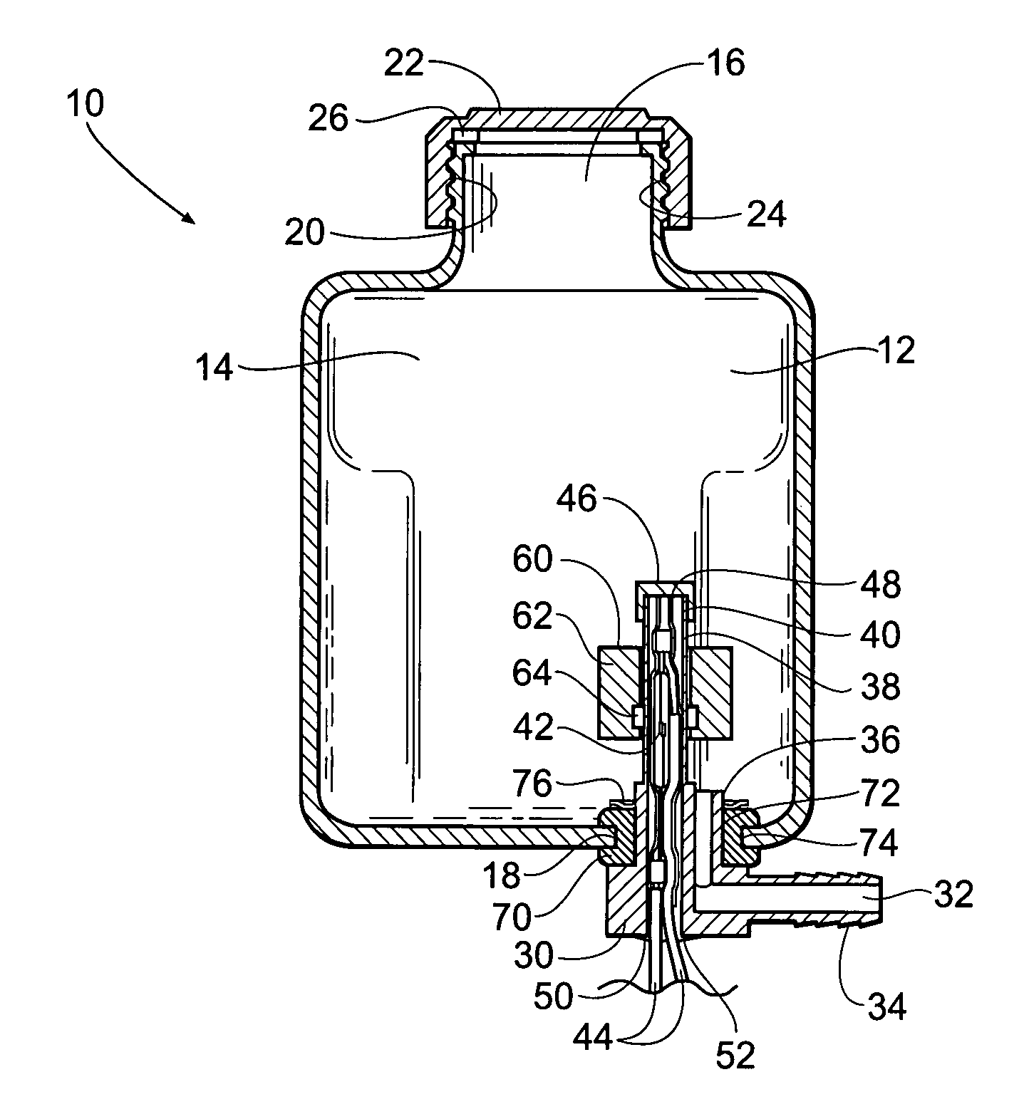
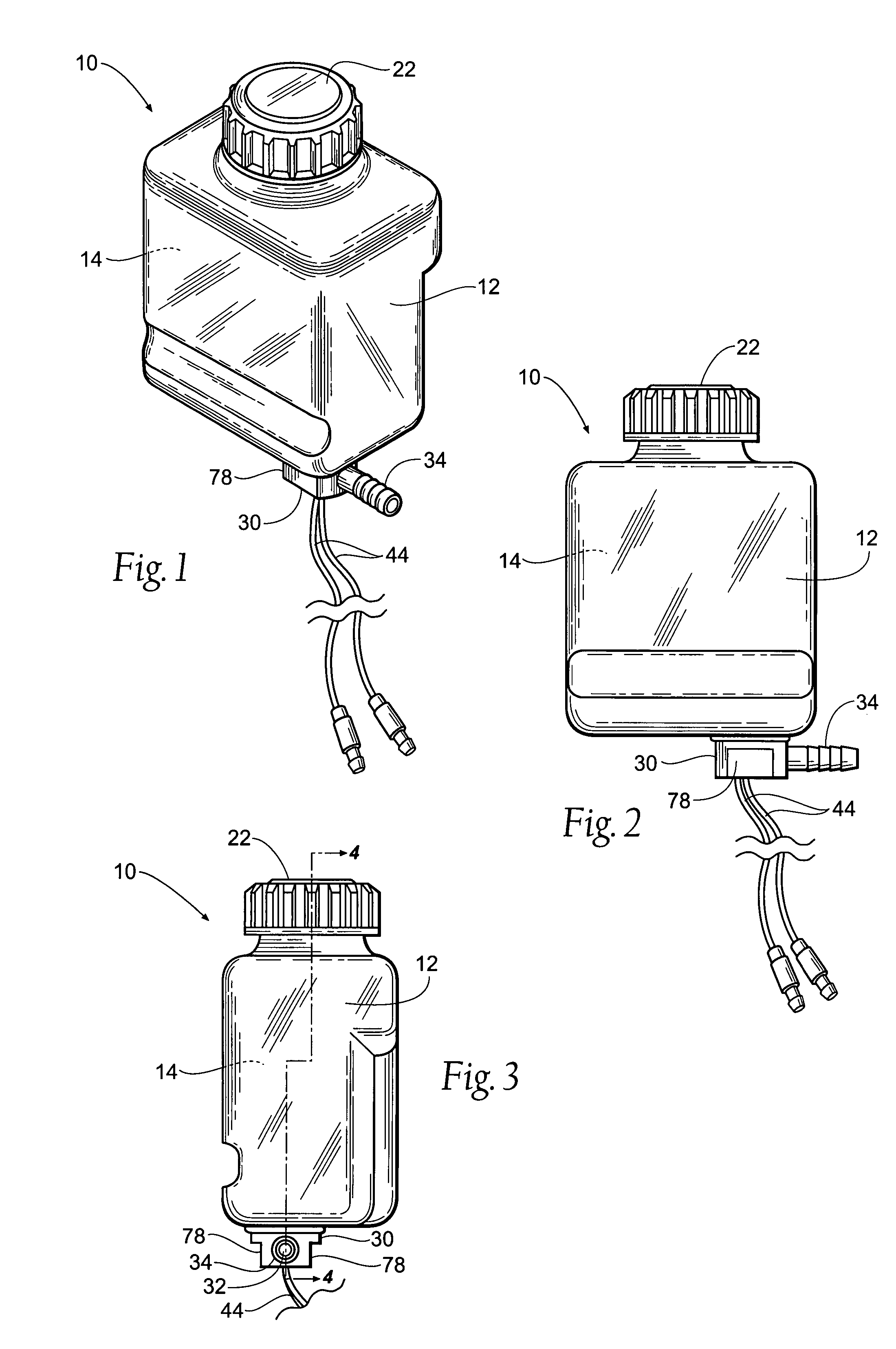
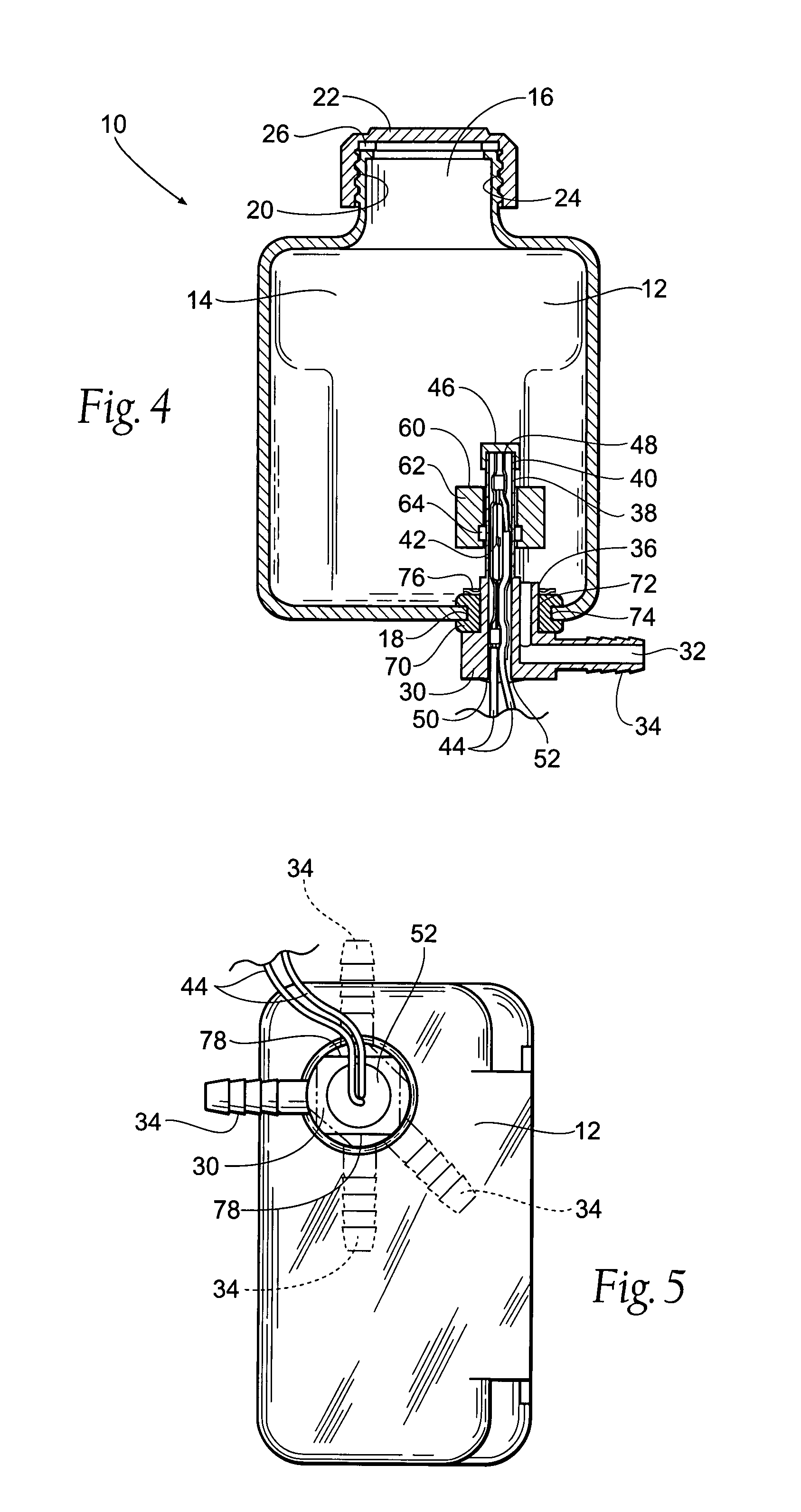
[0020]Referring now to FIGS. 1, 2, 3 and 4 the reservoir assembly of the present invention will be designated generally with the reference numeral 10. The assembly 10 includes a reservoir 12 having an interior volume 14, an upper opening 16 and a lower opening 18. The reservoir 12 can have any shape or size and be constructed from any material. In the preferred embodiment, the reservoir 12 has generally rectangular top, bottom and side walls and is constructed from a suitable plastic material such as polypropylene. A mating thread 20 is formed at the upper opening 16 for receiving a cap 22 having threads 24. A gasket 26 may be p...
PUM
 Abstract
Description
Claims
Application Information