Method for reducing the radiation load by a mobile radio terminal with directional emission, and a mobile radio terminal with directional emission

a mobile radio terminal and radiation load technology, applied in the direction of radio transmission, transmission, substation equipment, etc., can solve the problems of unsatisfactory radio-frequency irradiation of the head together, local temperature increase in the head, and possible human health effects that have not yet been scientifically verified, etc., to achieve convenient call-up, improve the rate and accuracy of adjustment, and improve the effect of setting speed

Inactive Publication Date: 2009-06-23
INFINEON TECH AG
View PDF18 Cites 4 Cited by
  • Summary
  • Abstract
  • Description
  • Claims
  • Application Information

AI Technical Summary

Benefits of technology

[0036]The method according to the invention is accordingly based on an antenna with a directional characteristic in a mobile station in a mobile radio system, which can be adjusted as a function of the direction, in particular in the horizontal direction. According to a first aspect of the invention, different variables are determined in a first step for different alignments of the main lobe direction of the antenna: a first variable which is characteristic of the signal strength and a second variable which is characteristic of the signal quality. In a further step, a preferred alignment is determined by evaluation of the determined values of the above variables for different alignments of the antenna. The main lobe direction can then be set in a further step from the knowledge of the determined preferred alignment, such that this main lobe direction matches the preferred alignment. This alignment allows optimum reception and, in general, an optimum transmission response as well, with respect to the associated fixed station. This is based on the fact that the antenna directional characteristic for reception and transmission is in general the same, or is at least very similar. The emitted radiated power from the mobile station can thus always be set to the minimum required value, thus reducing the radiation load.
[0050]According to one preferred method variant, the emitted power can be reduced following adjustment of the main lobe direction. The reduction in the emitted power is then restricted, for example, by a required maximum permissible bit error rate. This offers the advantage that a minimum emitted power value can be achieved after completion of the adjustment algorithm—matched to the adjustment result.

Problems solved by technology

Since mobile telephones are normally used against the ear and against the head when setting up and maintaining communication connections, this equally results in undesirable radio-frequency irradiation of the head together with the organs located in it, for example the brain and the eyes.
Depending on the intensity of the irradiation, this leads to a local temperature increase in the head, associated with possible damage to the tissue (microwave effect).
Furthermore, so-called non-thermal effects are also currently being discussed, whose possible effects on human health it has not, however, yet been finally possible to verify scientifically.
The greatest problem with this method is often the immediate area surrounding the antenna: for example, the earthing configuration, which is normally too small and is thus poor for the frequency band, which is in the Gigahertz range, in the form of the mounting board in the mobile appliance results in major interaction between the antenna and the area surrounding the antenna or the mobile appliance.
This interaction means that any change in the area surrounding the mobile appliance, which also includes the way in which the mobile appliance is fixed, in some circumstances may even lead to an increase in the radiation load, since the entire telephone then acts as an antenna and can contribute to emission in any direction, that is to say in particular it can even lead to increased emission in the direction of the user.
However, in this method, interference influences can adversely affect the optimum antenna alignment as a result of the directional power measurement for location of the fixed station.

Method used


Image

  • Method for reducing the radiation load by a mobile radio terminal with directional emission, and a mobile radio terminal with directional emission
  • Method for reducing the radiation load by a mobile radio terminal with directional emission, and a mobile radio terminal with directional emission
  • Method for reducing the radiation load by a mobile radio terminal with directional emission, and a mobile radio terminal with directional emission

Examples


Embodiment Construction

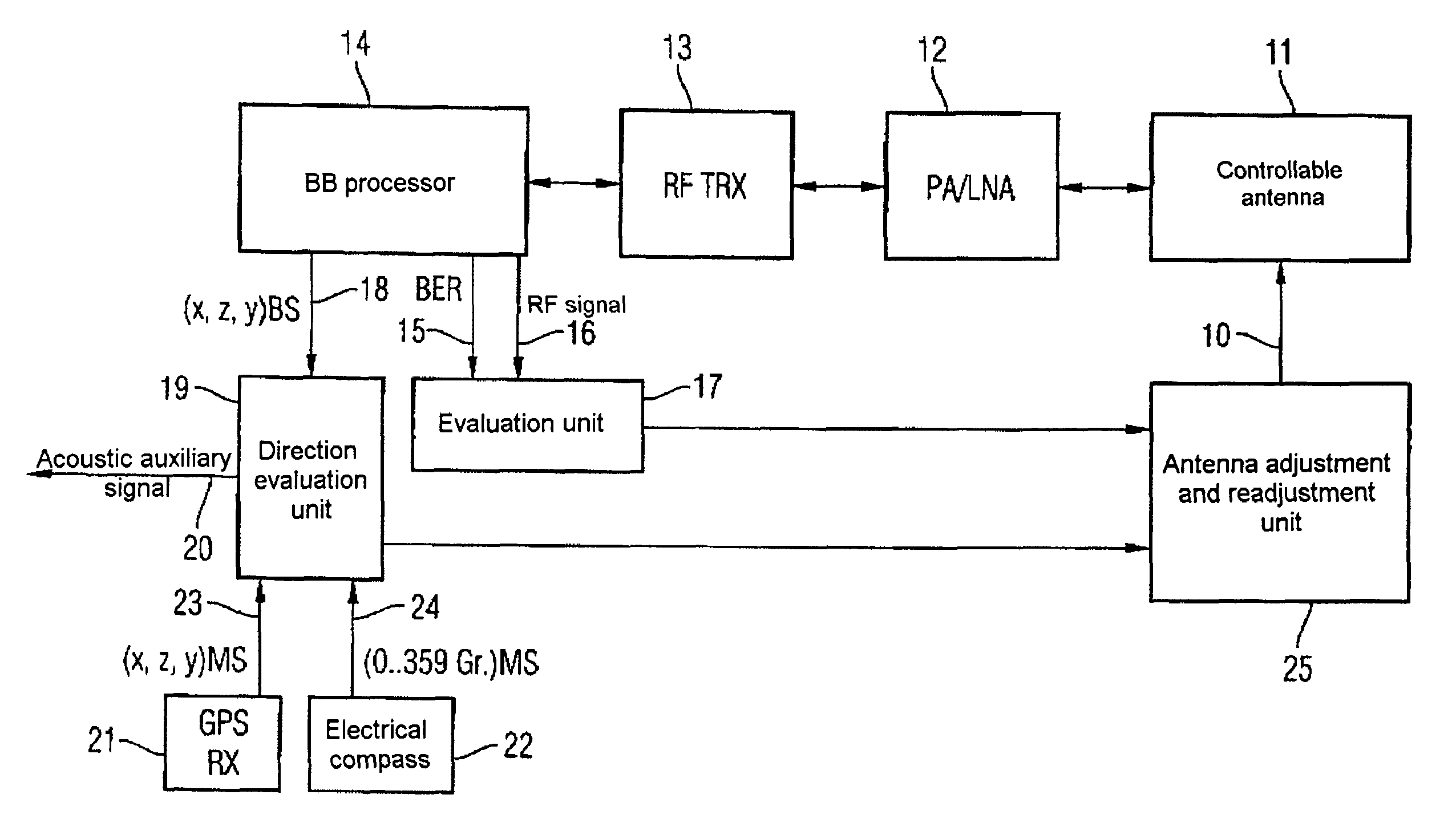
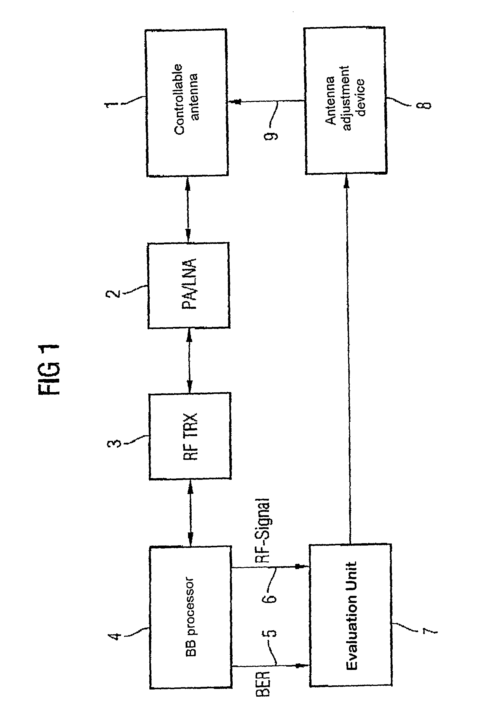
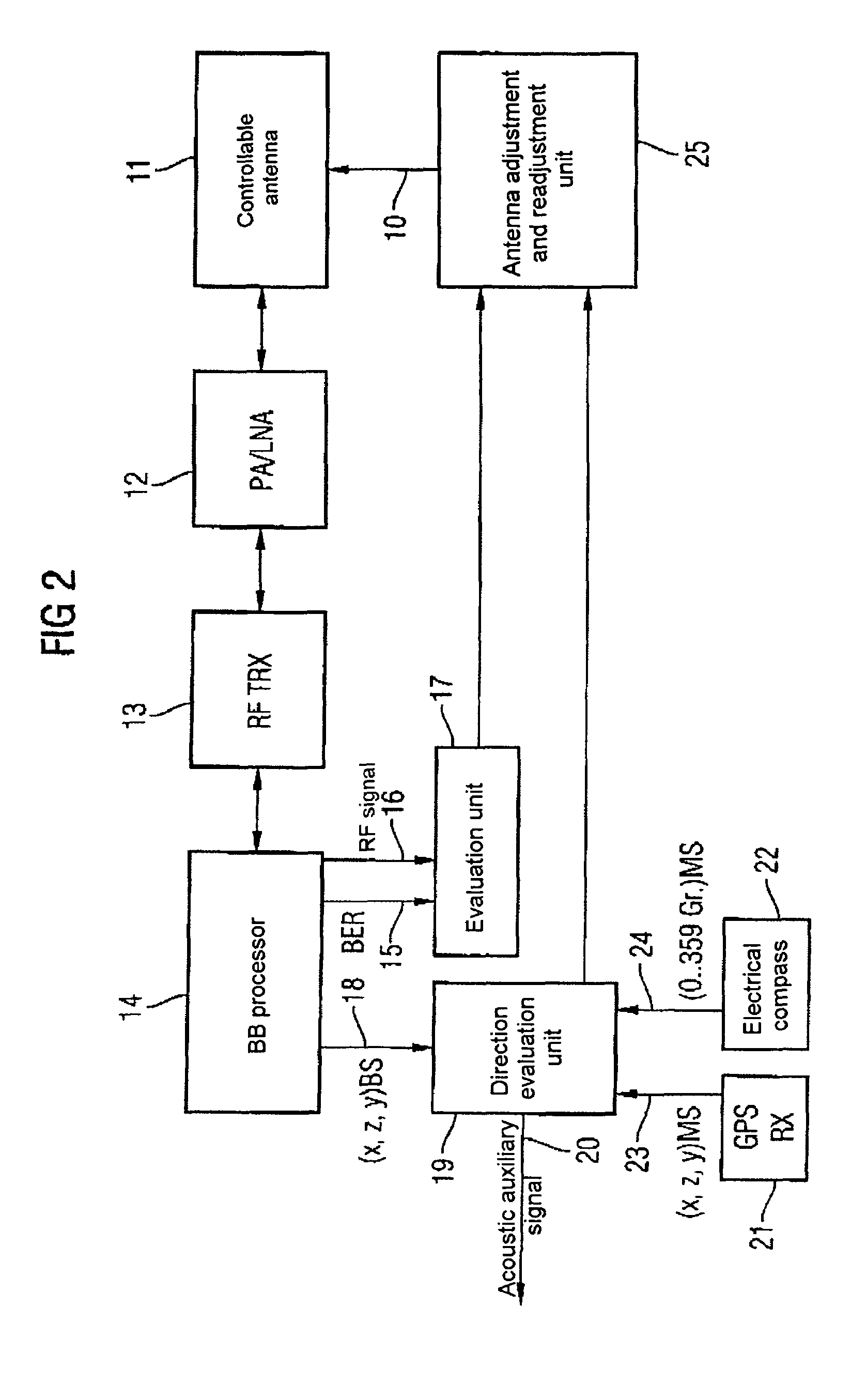
[0055]According to the block diagram illustrated in FIG. 1, an apparatus according to the invention and based on the first exemplary embodiment is designed as follows: An antenna 1 whose directional characteristic is controllable is electrically connected bidirectionally to an amplifier block 2. The amplifier block 2 is itself bidirectionally connected to a radio-frequency transmitter / receiver circuit 3, also referred to as an RF transceiver (RF-TRX). The RF transceiver 3 is also bidirectionally connected to a baseband processor 4 (BB processor). The output variables from this baseband processor 4 are the bit error rate 5 (BER) and the field strength 6 (RF signal) of the received signal, and these variables are supplied as input variables to an evaluation unit 7. The output of the evaluation unit 7 is connected to an antenna adjustment device 8, which in turn supplies a control signal 9 to the control input of the controllable antenna 1.

[0056]The antenna 1 with an adjustable directi...


PUM


Abstract

In a method for alignment of an antenna (1) with an adjustable directional characteristic in a mobile station in a mobile radio system, the alignment process is based on determination of two variables as a function of the direction, with the first variable being characteristic of the signal strength (6) and the second variable being characteristic of the signal quality (5, 15), and their evaluation (7). Furthermore, it is possible to make use of position information and alignment information relating inter alia to satellite-based navigation systems, and to take account of the alignment of the user.

Description

PRIORITY[0001]This application claims priority to German application no. 103 28 570.9 filed Jun. 25, 2003.TECHNICAL FIELD OF THE INVENTION[0002]The present invention relates to a method and an arrangement for alignment of an antenna with an adjustable directional characteristic in a mobile station in a mobile radio system.BACKGROUND OF THE INVENTION[0003]Depending on the required selected power class, mobile telephones emit transmission power levels of up to 2 W via the transmitting antenna. Particularly in the edge of the supply area of a radio cell or when transmission is interfered with by multipath propagation, the network system administration for the mobile telephone will often choose the highest power class in order to set up and maintain the connection.[0004]If the antenna is in the form of a (shortened) monopole which is fitted externally on the telephone and if there is no interference in the environment in the immediate near field of the antenna, omnidirectional emission ...

Claims


Application Information

Patent Timeline
Patent Type & Authority Patents(United States)
IPC IPC(8): H04B7/185H01Q1/12
CPCH01Q1/1257
Inventor FENK, JOSEFKRONBERGER, RAINER
Owner INFINEON TECH AG
Why Eureka
Try Eureka