Process and arrangement for confocal microscopy

a confocal microscopy and confocal light technology, applied in the field of confocal light microscopy, can solve the problems of insufficient, inability to achieve the effect of precise image evaluation, and gain of impression

Inactive Publication Date: 2010-09-14
CARL ZEISS MICROSCOPY GMBH
View PDF27 Cites 0 Cited by
  • Summary
  • Abstract
  • Description
  • Claims
  • Application Information

AI Technical Summary

Benefits of technology

[0014]On this basis, the primary object of the invention is to further develop a process for laser scanning microscopy of the type described above in such a way that the radiation loading of the specimen is reduced and a more precise image evaluation is achieved.

Problems solved by technology

With light microscopy, it is not possible, for example, to gain an impression of the spatial structure of the rough surface of a specimen at high magnification because only a small area of the specimen can be shown in sharp focus, while details located deep in the surface are imaged in a blurry manner because of the high scattered light component and deficient axial resolution.
However, a disadvantage consists in that the respective specimen is acted upon over the entire scanning region by the laser radiation that is generated in the laser module and coupled into the scanning unit.
The entire scanning region is therefore exposed to a relatively high radiation loading which leads to unwanted effects and insufficient results particularly when investigating living organisms.
A further disadvantage consists in that radiation emitted and / or reflected from a determined location on a specimen cannot be detected and evaluated in a definite manner when the specimen is excited with different wavelengths such as those of the above-mentioned laser lines, since the “bleed-through” effect occurs between the individual spectral lines.

Method used


Image

  • Process and arrangement for confocal microscopy
  • Process and arrangement for confocal microscopy
  • Process and arrangement for confocal microscopy

Examples


Embodiment Construction

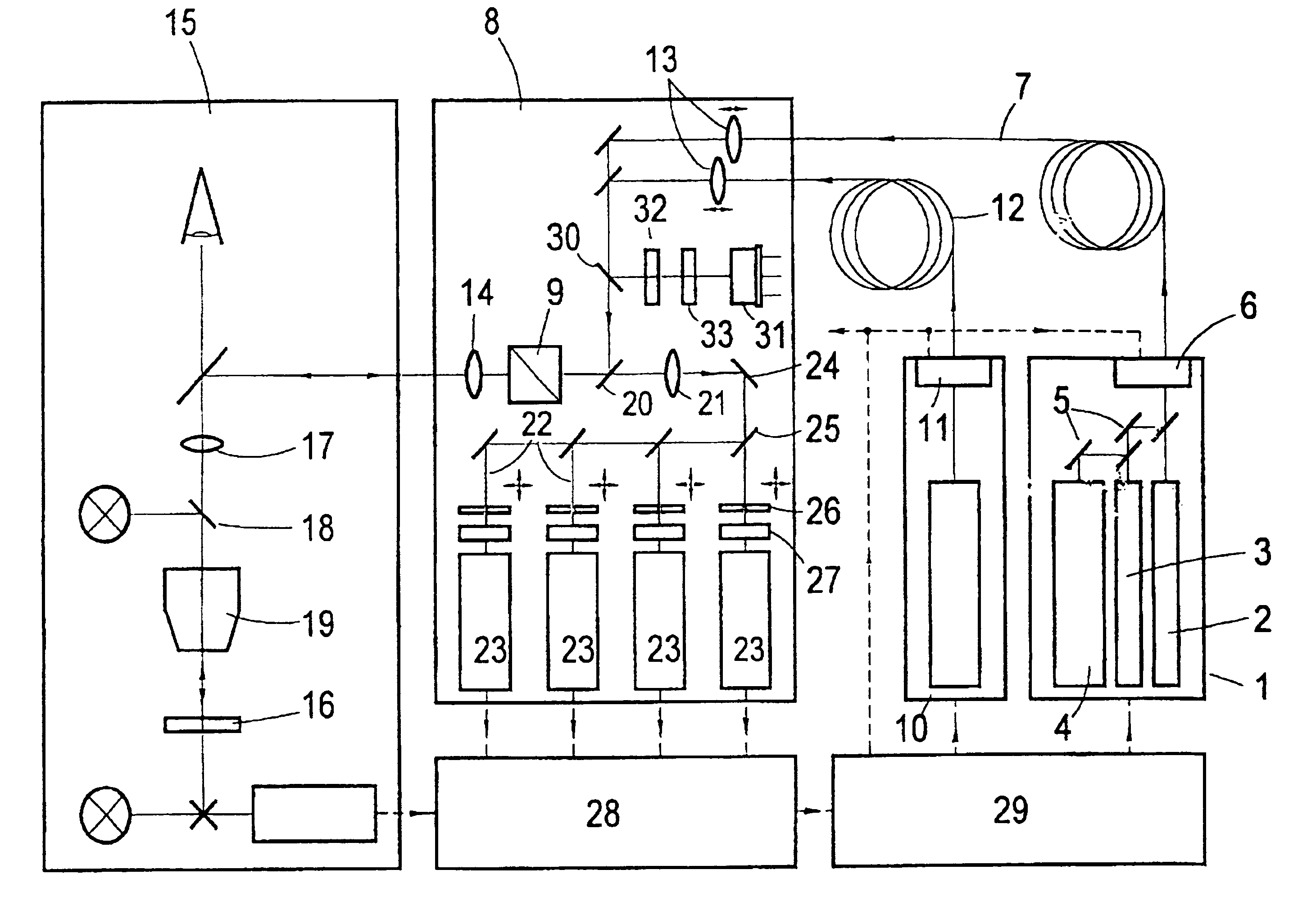
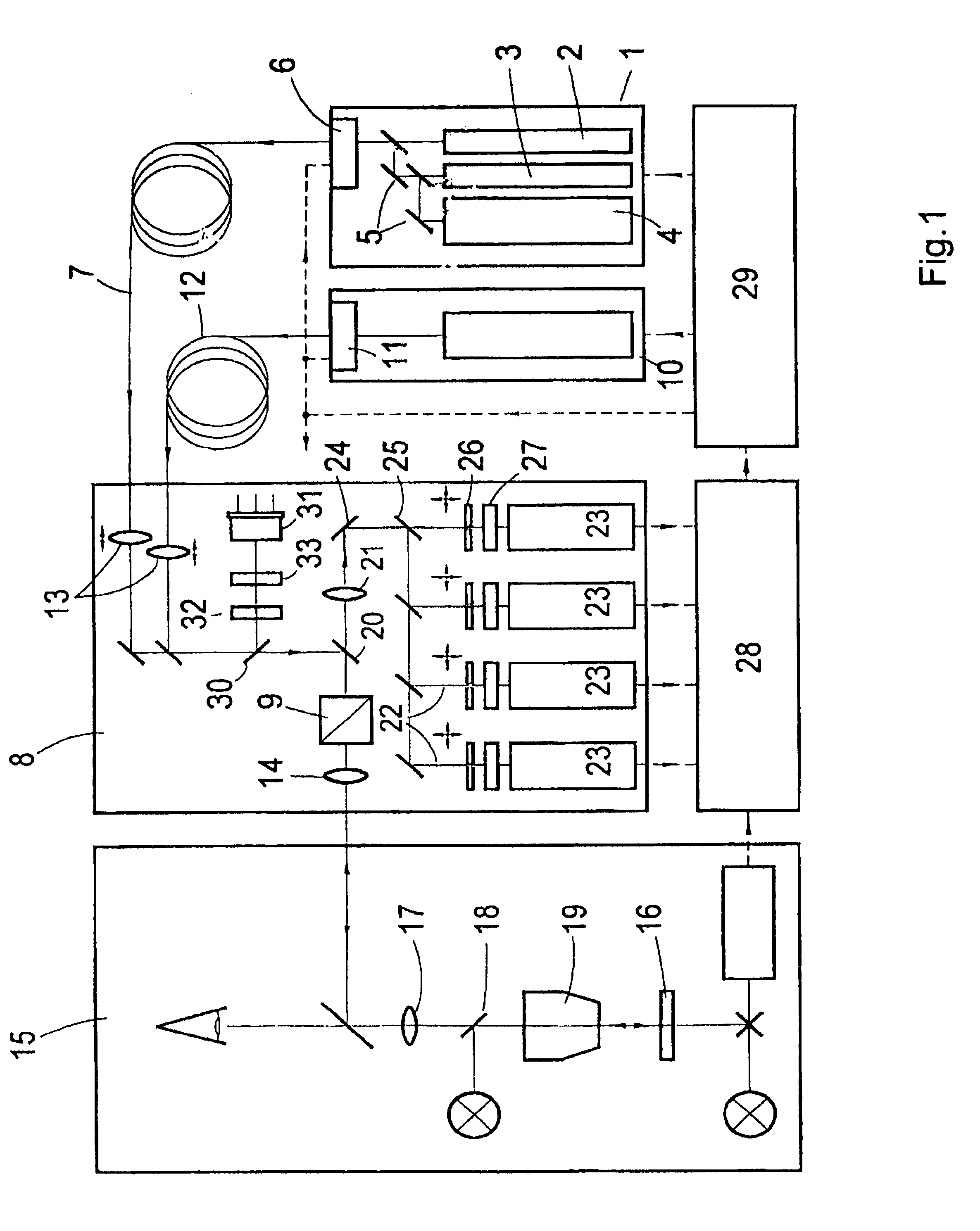
[0041]FIG. 1 shows a laser module 1 which is outfitted with lasers 2, 3 and 4 for generating laser light in the visible range with wavelengths of 633 nm, 543 nm and 458 nm. By mean of a plurality of beam combiners 5, an AOTF 6 and a fiber 7, the radiation emitted by these lasers is coupled into a scanning device 8 which is outfitted with a unit 9 deflecting beams in the x and y coordinates.

[0042]A UV laser whose light is coupled into the scanning device 8 via an AOTF 11 and a light-conducting fiber 12 is provided in a second laser module 10.

[0043]In the two beam paths, collimating optics 13 are provided subsequent to the light-conducting fibers 7 and 12, wherein the distance between the collimating optics 13 and the respective end of the fiber can be changed and the collimating optics 13 are coupled for this purpose with a controllable adjusting device (not shown in the drawing).

[0044]The laser radiation is coupled into the beam path of the schematically shown microscope 15 by the b...


PUM

PropertyMeasurementUnit
wavelengthsaaaaaaaaaa

Abstract

A process for confocal microscopy is disclosed in which laser light is coupled into a microscope beam path, directed successively with respect to time onto different locations of a specimen, and an image of the scanned plane is generated from the light reflected and emitted by the irradiated locations. A change in the spectral composition and in the intensity of light isare carried out during the deflection of the laser beam from location to location, while the deflection continues in an uninterrupted manner. In this way , so that at least two adjacent locations of the specimen located next to one another are acted upon by light with different spectral characteristics and by laser radiation of different intensity. By periodically interrupting the coupling in of the laser light during the deflection of the microscope beam path, it is made possible that only selected portions of the image field are acted upon by the laser radiation. A laser scanning microscope for carrying out this process is also disclosed. A laser scanning microscope for carrying out this process is also disclosed.

Description

BACKGROUND OF THE INVENTION[0001]a) Field of the Invention[0002]The invention is directed to a process for confocal microscopy in which laser light of different spectral ranges is coupled into a microscope beam path deflected in at least two coordinates and is directed successively with respect to time onto locations of a specimen, wherein the specimen is acted upon, location by location and line by line, by the laser light in at least one plane and an image of the scanned plane is generated from the light reflected and / or emitted by the irradiated locations. The invention is further directed to a laser scanning microscope for carrying out this process.[0003]b) Description of the Related Art[0004]While conventional light microscopy only enables the optical acquisition of one imaging plane, confocal microscopy, as a special further development of light microscopy, offers the possibility of imaging and measuring microstructures also in the Z spatial axis. With light microscopy, it is ...

Claims


Application Information

Patent Timeline
Patent Type & Authority Patents(United States)
IPC IPC(8): G01N21/64G01N21/27G01J3/30G02B21/00
CPCG01N21/645G02B21/0056G02B21/0064G02B21/0076G02B21/0084
Inventor SIMON, ULRICHTILLE, SEBASTIANMOEHLER, GUNTERWILHELM, STEFANMEISEL, ULRICHSTELZER, ERNST
Owner CARL ZEISS MICROSCOPY GMBH
Why Eureka
Try Eureka