Computed tomography and positioning of a volume to be imaged

a computed tomography and volume technology, applied in tomography, radiation beam directing means, applications, etc., can solve the problems of increasing the patient's total radiation dose, requiring extra time from both the patient and the personnel, and proving inaccurate positioning by even an experienced person, so as to achieve the effect of not increasing the radiation load

Active Publication Date: 2022-03-01
PLANMECA
View PDF7 Cites 0 Cited by
  • Summary
  • Abstract
  • Description
  • Claims
  • Application Information

AI Technical Summary

Benefits of technology

[0008]The solution according to the invention offers a novel kind of visual and easy-to-use possibility to direct the volume being imaged at a desired point in the patient's anatomy and in a way which does not increase radiation load. In directing imaging, it is possible to use several but also only one display which shows the above-mentioned at least two images. The display or displays can be positioned in a separate space protected from radiation and the directing can be performed from there, whereby there is no need to wait for the assisting person to exit from the imaging set for shelter from radiation after the directing.

Problems solved by technology

Wishing to image a certain partial volume but simultaneously trying not to image anything diagnostically inessential naturally causes a problem of positioning the anatomy being imaged to the imaging apparatus such that specifically the desired volume of the anatomy can be imaged.
Directing such lights to a desired point in the anatomy always takes some time and, when the whole process is based mostly on ‘educated guess’ on the position of the volume desired to be imaged in relation to the external features of the anatomy, the positioning by even an experienced person can prove to having been inaccurate.
In such cases, it is possible that the imaging must be renewed, which increases the patient's total radiation dose, is in general frustrating and requires extra time from both the patient and the personnel.
However, the quality of such scout images is typically quite poor and, on the other hand, even a small extra radiation dose does in any case always increase the radiation load.

Method used


Image

  • Computed tomography and positioning of a volume to be imaged
  • Computed tomography and positioning of a volume to be imaged
  • Computed tomography and positioning of a volume to be imaged

Examples


Embodiment Construction

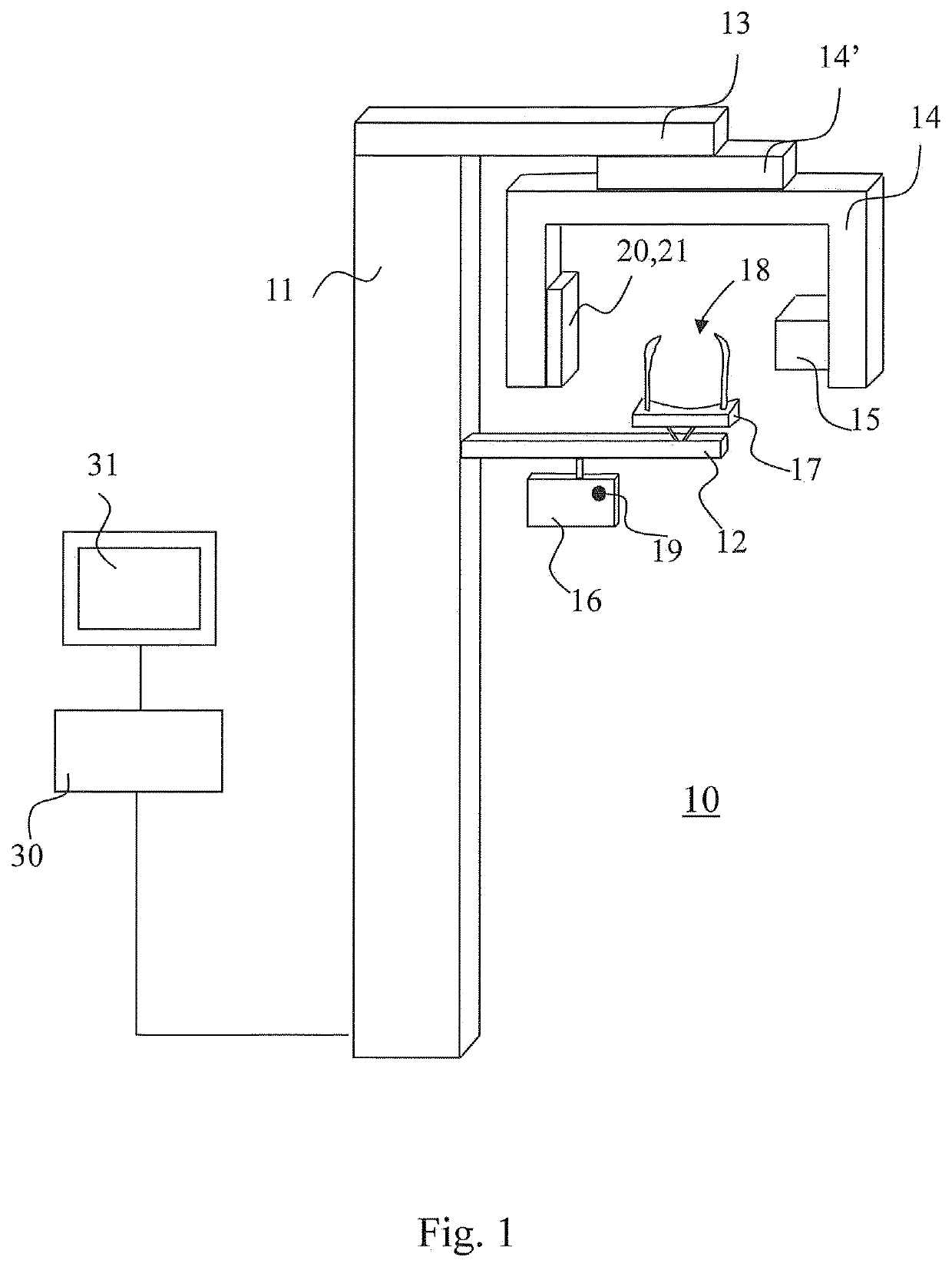
[0015]FIG. 1 shows a basic structure of one apparatus suitable for use in computed tomography. The apparatus includes a vertical support construction 11 from which horizontally extends an arm 12 supporting patient support means and an arm part 13 which supports a structure supporting imaging means of the apparatus, an arm part 14. In the structure according to FIG. 1, the arm part 14 supporting the imaging means is arranged rotatable via a second rotatable arm part 14′, which solution offers versatile possibilities for moving the imaging means. To the arm part 14 supporting the imaging means are arranged at a distance from each other an X-ray source 15 and a receiver of X-ray image information 21 which have been positioned to the apparatus with respect to a patient support means 17 such that to the apparatus is formed an imaging station 18 which is positioned between the X-ray source 15 and the receiver of X-ray image information 21 such that a beam produced by the X-ray radiation s...


PUM


Abstract

The invention relates to positioning a volume to be imaged for computed tomography imaging. According to the invention, at least two optical cameras (22) are used for taking a photo or for live imaging an anatomy from different directions. A volume positioning indicator (42) is shown in connection with these images, the volume positioning indicator (42) indicating the location of the volume within the area imaged by the cameras (22) to get imaged by the computed tomography imaging apparatus (10).

Description

FIELD OF INVENTION[0001]The invention relates to positioning a volume to be imaged for computed tomography imaging or, to put it in other words, directing imaging to a desired volume in an anatomy. The invention particularly relates to the computed tomography imaging of the human or animal cranial area.BACKGROUND OF INVENTION[0002]Medical computed tomography imaging (CT imaging) is a form of X-ray imaging in which a volume to be imaged is irradiated from different, directions and, from the data thus acquired, a desired two- or three-dimensional image is reconstructed afterwards. When X-ray imaging a person, the imaging must be implemented by as small a radiation dose as possible to still enable diagnosis. Due to this, one e.g. tries to keep the size and shape of the volume to be imaged as small as possible. For example, it is typical for dental cone-beam computed tomography (CBCT) that it does not produce image information of an anatomy for reconstructing a cross section of volume o...

Claims


Application Information

Patent Timeline
Patent Type & Authority Patents(United States)
IPC IPC(8): A61B6/00A61B6/14A61B5/00A61B6/03A61B6/08
CPCA61B6/14A61B5/4542A61B6/032A61B6/08A61B6/461A61B6/469A61B6/4441A61B6/03A61B6/5264A61B6/501
Inventor NYHOLM, KUSTAASEPPALA, LAURIPIHLAJAMAKI, TERO
Owner PLANMECA
Why Eureka
Try Eureka