
Automobiles Having a Radiant Barrier

a technology of radiant barrier and automobile, which is applied in the field of automobiles, can solve the problems that one side of the film does not allow oxygen diffusion into the film, and achieve the effects of reducing the solar load of the automobile, high efficiency, and high light transmission

Active Publication Date: 2011-01-20
WILSON STEPHEN S +2
View PDF15 Cites 1 Cited by
  • Summary
  • Abstract
  • Description
  • Claims
  • Application Information

AI Technical Summary

Benefits of technology

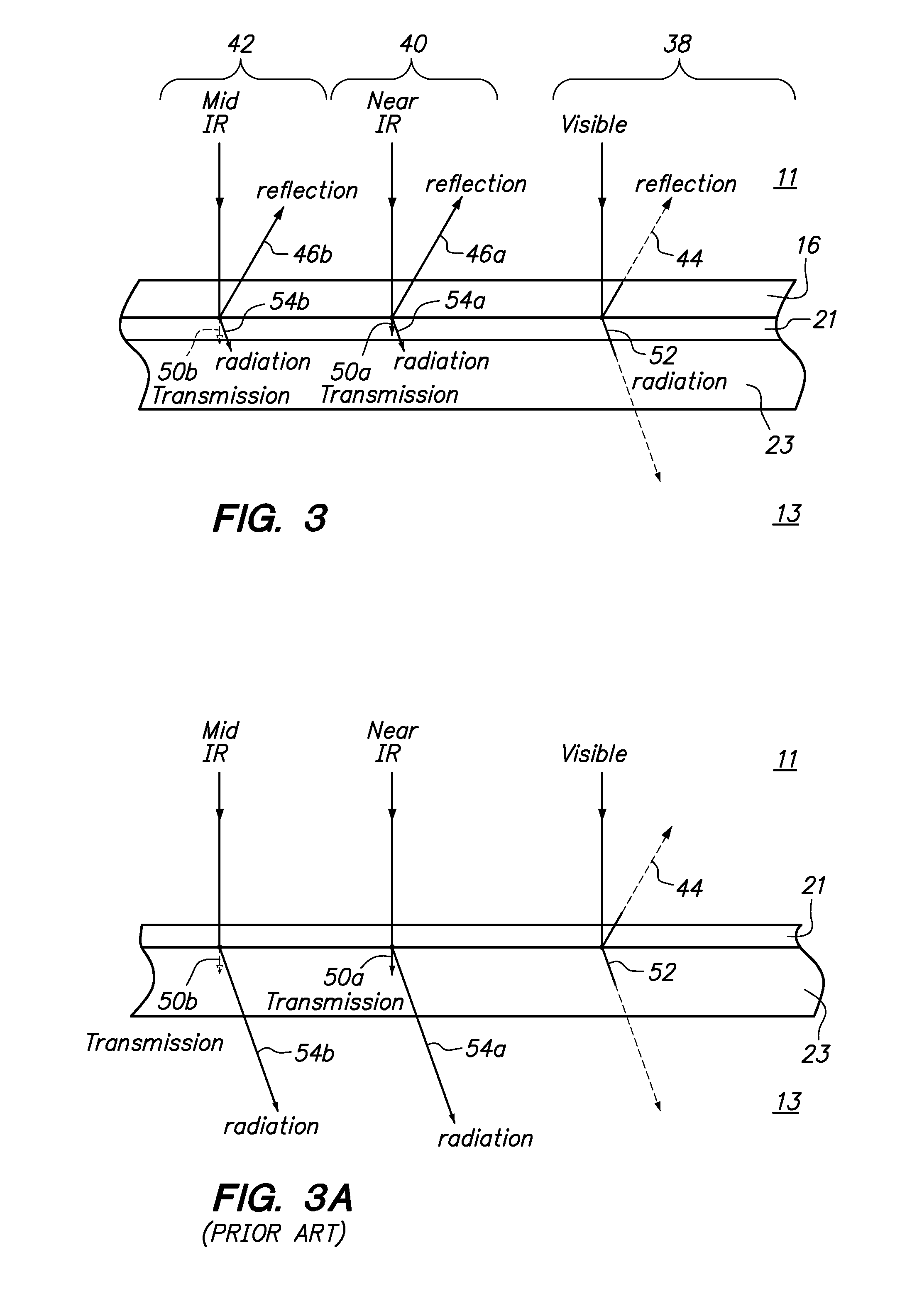
[0012]A vehicle is provided having a high efficiency solar control system. The solar control system may comprise a metallic panel which is coated with paint. A film may be mounted to the exterior side of the paint, namely, the side closer to the environment. The metallic panel of the vehicle may be any portion of the vehicle such as the roof, hood, trunk, door or any other surface area upon which the sun's rays are exposed. The film may have high transmission of light in the visible range such that the color of the paint may be transmitted or seen through the film. Also, the film may reflect a high percentage of light in the near infrared range and the mid infrared range back into the environment. As such, the solar load on the automobile is reduced by the amount of solar radiation in the near infrared range and the mid infrared range reflected back into the environment. Preferably, the film is mounted to the roof of the vehicle such that the solar load on the cabin of the automobile is reduced by the amount of reflected infrared radiation.
[0013]The film may additionally have a plurality of sacrificial layers which have a high transmission value with respect to the visible range and the near and mid infrared ranges. The topmost sacrificial layer may be removed or peeled away when it has been unacceptably degraded due to environmental elements (e.g., chips, oxidation, etc.) thereby exposing a fresh new topmost layer. Additionally, the additional sacrificial layers mitigate oxidation of a silver layer embedded within the film. In particular, the film may be mounted to a painted surface of the vehicle. As such, one side of the film does not allow diffusion of oxygen into the film since oxygen cannot diffuse through the painted surface and underlying metallic panel. On the other side of the film (or the silver layer(s)), a thick stack of sacrificial layers may be formed. Although oxygen may be diffused through the sacrificial layers, such diffusion of oxygen through the sacrificial layers may be slowed down by increasing the thickness of the sacrificial layers. Either or both the number of sacrificial layers may be increased or decreased as appropriate or the thickness of each of the sacrificial layers may be increased or decreased to bring the rate of oxygen diffusion to an acceptable level. The silver layer is disposed between the glass and the thick stack of sacrificial layers which protects the silver layer from oxidation.
[0015]The film may comprise an infrared reflecting layer defining an interior side and an exterior side. The interior side of the infrared reflecting layer may be attached to the exterior side of the paint layer. The infrared reflecting layer may have an embedded infrared reflecting core which comprises one or more layers of silver and one or more layers of dielectric for reflecting infrared radiation. The silver layer and dielectric layer may alternate. The film may further comprise one or more protective layers removeably attached to the exterior side of the infrared reflecting layer for mitigating oxidation of the silver layer and for providing a sacrificial top layer which can be removed when the top layer is damaged due to UV exposure or oxidation. The protective layers may be peelably adhered to one another. An exterior side of each of the protective layers may have an ultraviolet light absorbing hard coat.
[0019]A method for reducing solar radiation load within an automobile is also disclosed. The method may comprise the steps of providing a film for reflecting infrared radiation wherein the film comprises an infrared reflecting layer and one or more protective layers. The infrared reflecting layer may define an interior side and an exterior side. The infrared reflecting layer may have an embedded infrared reflecting core which comprises one or more layers of silver and one or more layers of dielectric for reflecting infrared radiation. The one or more protective layers may be removeably attached to the exterior side of the infrared reflecting layer for mitigating oxidation of the silver layer and for providing a sacrificial top layer which can be removed when the top layer is damaged due to UV exposure or oxidation. The method may further comprise the step of attaching an interior side of the infrared reflecting layer to an exterior side of the automobile.
[0024]The film may comprise an infrared reflecting core which comprises one or more layers of silver and one or more layers of dielectric for reflecting infrared radiation, the infrared reflecting core defining opposed first and second sides, a first protective layers attached to the first side of the infrared reflecting layer wherein the first protective layer has a first thickness, a second protective layer attached to the second side of the infrared reflecting layer and the paint layer wherein the second protective layer has a second thickness and the first thickness is greater than the second thickness, and wherein the first and second protective layers provide structural support to the one or more silver layers and the thicker first protective layer mitigates oxidation of the one or more silver layers caused by oxygen diffusion through the first protective layer.

Problems solved by technology

As such, one side of the film does not allow diffusion of oxygen into the film since oxygen cannot diffuse through the painted surface and underlying metallic panel.

Method used


Image

  • Automobiles Having a Radiant Barrier
  • Automobiles Having a Radiant Barrier
  • Automobiles Having a Radiant Barrier

Examples


Embodiment Construction

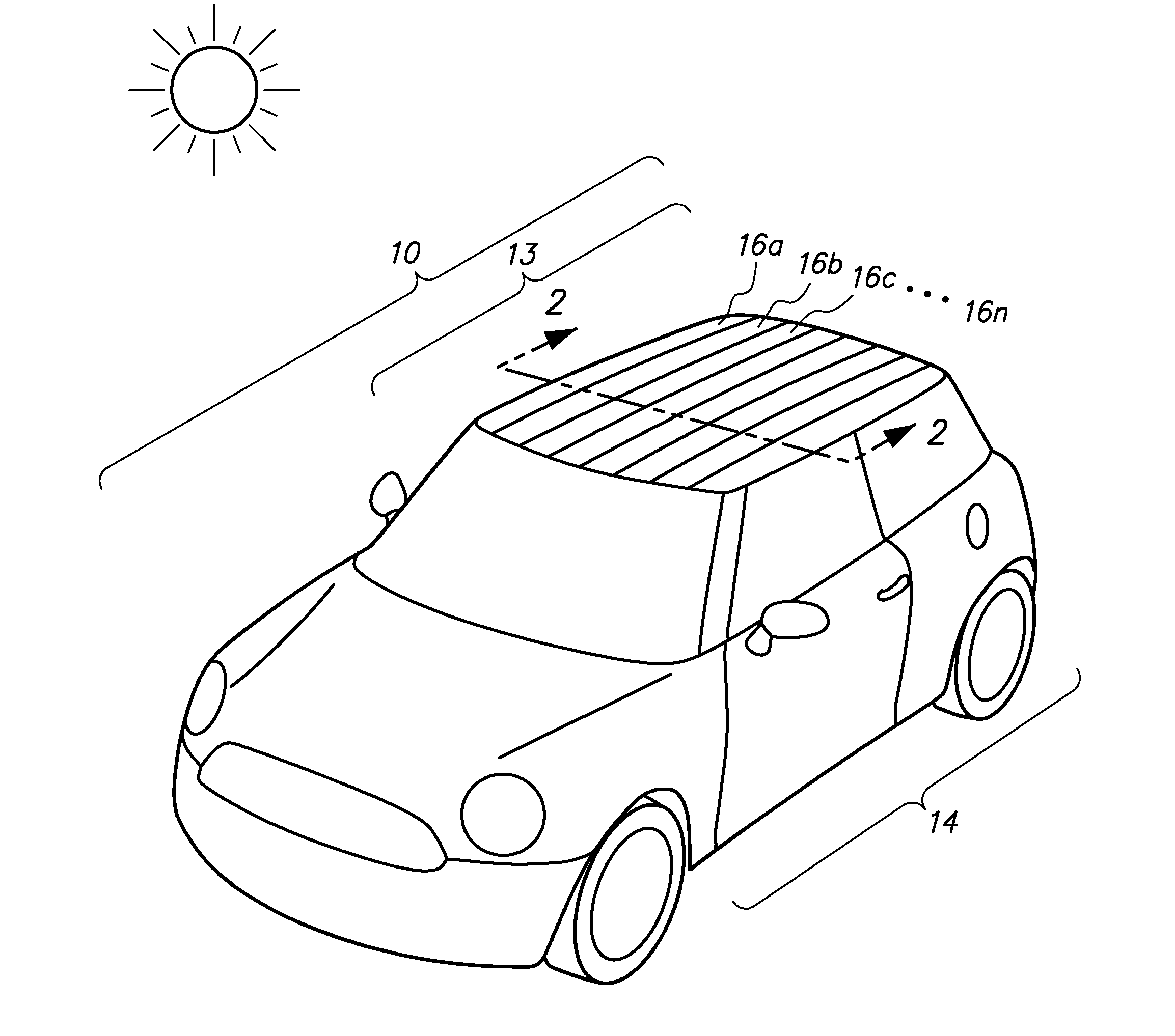
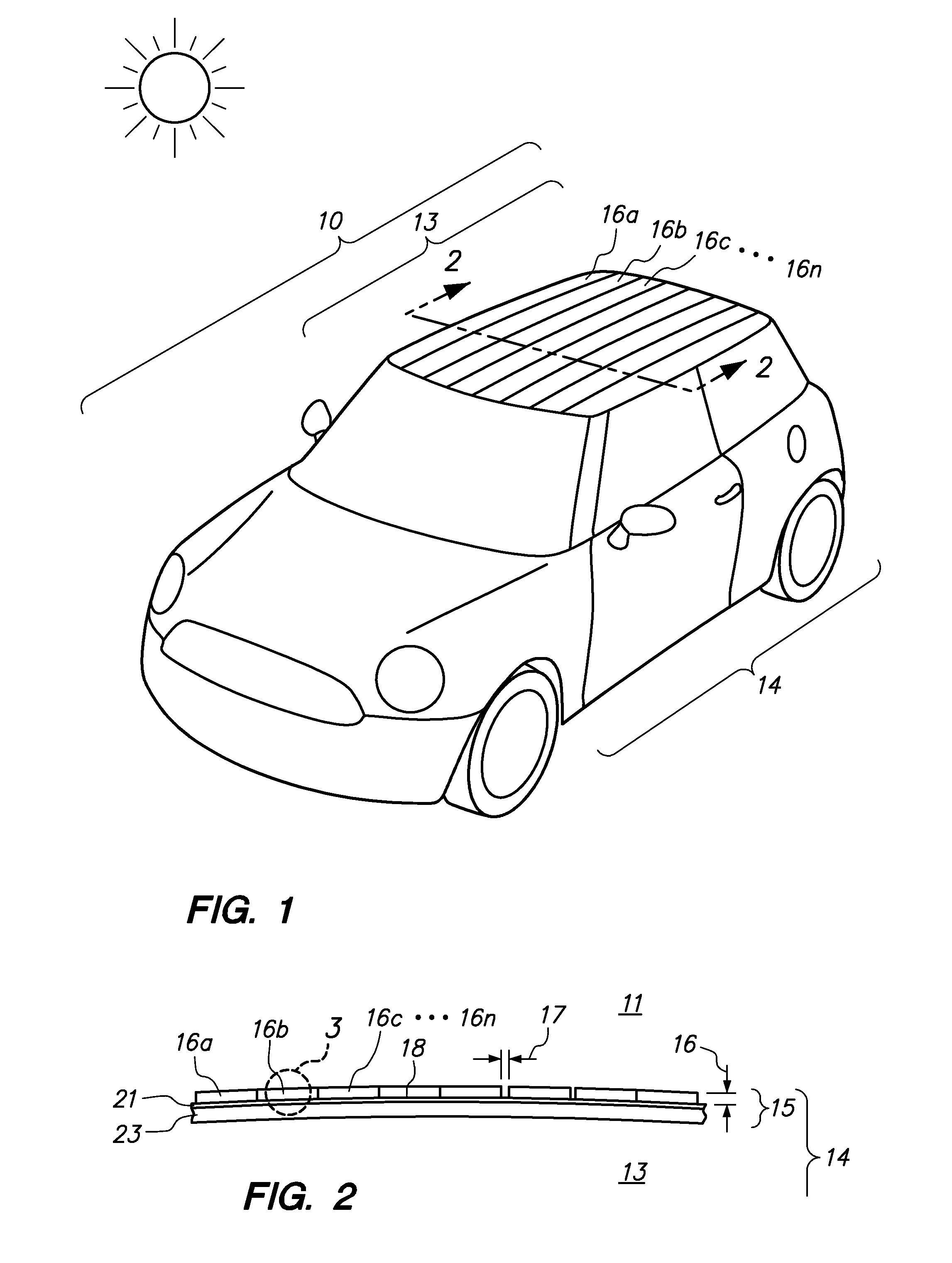
[0033]Referring now to FIG. 1, an automobile 10 having a roof 15 is shown. The roof 15 protects the occupants from environmental elements (e.g., wind, rain, sun, etc.). As shown in FIG. 2, the roof 15 may have a film 16 (or a plurality of film pieces) attached to an exterior side 18 of a painted layer 21 of the roof 13. The film 16 may be generally optically transparent in the visible wavelengths and generally reflect radiation in the non-visible or infrared wavelengths. The sun's rays transmit solar radiation both in the visible light range and also in the infrared range. A majority of the radiation in the infrared range may be reflected back to the exterior 11 of the cabin 14 by the film 16. A small portion of the energy may be absorbed by the paint layer 21 and the underlying panel 23 of the roof 13, converted into heat and re-radiated into the interior 13 of the cabin 14. Beneficially, the film 16 reduces the amount of solar radiation in the near and mid infrared ranges from bei...


PUM

PropertyMeasurementUnit
Dielectric polarization enthalpyaaaaaaaaaa
Transparencyaaaaaaaaaa
Lightaaaaaaaaaa

Abstract

An automobile or vehicle having a high efficiency solar control system is provided. The automobile may have a painted surface and a film mounted to its exterior side. The film may reflect solar radiation in the near and mid infrared ranges yet allow high transmission of light in the visible range such that the painted panel may be seen. The film may have a layer of silver which reflects the solar radiation in the near and mid infrared ranges. Since the silver is susceptible to oxidation and turns the silver into a black body which absorbs the near and mid infrared radiation, the film may be designed to slow the rate of oxidation of the silver layer to an acceptable level. The silver layer may be sandwiched between the glass which does not allow oxygen to diffuse there through and reach the layer of silver and a stack of sacrificial layers having a certain thickness which slows down the rate of oxygen diffusion to an acceptable level.

Description

CROSS-REFERENCE TO RELATED APPLICATIONS[0001]Not ApplicableSTATEMENT RE: FEDERALLY SPONSORED RESEARCH / DEVELOPMENT[0002]Not ApplicableBACKGROUND[0003]The present invention relates to an automobile having a film mounted to its painted surface for reducing solar radiation load yet allowing the paint's color to shine through the film.[0004]Direct sunlight on a painted surface of an automobile or vehicle may cause drivers to use the air conditioning system and / or use the air conditioning system at a higher level. The reason is that the paint and the underlying panel (e.g., metallic panel) may behave as a black body absorbing infrared radiation and re-radiating the absorbed infrared radiation as heat into the automobile cabin. Unfortunately, as a result, the air conditioning system may consume a large percentage of energy expended by the automobile in light of its overall energy consumption. By way of example and not limitation, the air conditioning system of the automobile may consume ap...

Claims


Application Information

Patent Timeline
IPC IPC(8): F21V9/04
CPCY10T428/1471B60R13/08
Inventor WILSON, STEPHEN S.WILSON, BARTWILSON, SETH
Owner WILSON STEPHEN S
Learn More