Method and arrangement for placing reel end shields

a technology of end shields and reels, applied in the directions of packaging, transportation and packaging, packaging, etc., can solve the problems high ancillary devices, and inability to meet the needs of high-wage countries, and achieve the effect of high wage level, convenient handling of end shields, and considerable savings

Active Publication Date: 2009-07-14
VALMET TECH INC
View PDF35 Cites 0 Cited by
  • Summary
  • Abstract
  • Description
  • Claims
  • Application Information

AI Technical Summary

Benefits of technology

[0012]The most important advantage of the method is the considerable savings that accrue from the fact that packing can be implemented with the aid of only a single industrial robot or portal manipulator. These are both, together with their ancillary devices, still expensive devices. The handling of the end shields is facilitated, because the end shields are brought to only one location within the reach of the end-shield setter. This makes it easier to plan the transportation of the end shields from the store to the point of use. The end shields can also be placed by hand, in which case only one operator supervising the equipment will be enough for placing the shields. If the reel is moved continuously over a direct path from one processing station to another, there is bound to be too great a distance from the inner end-shield placing station to the end-shield press station, so that in this case at least two operators will be required. This will not be possible in countries with a high wage level.

Problems solved by technology

These are both, together with their ancillary devices, still expensive devices.
This will not be possible in countries with a high wage level.

Method used


Image

  • Method and arrangement for placing reel end shields
  • Method and arrangement for placing reel end shields

Examples


Embodiment Construction

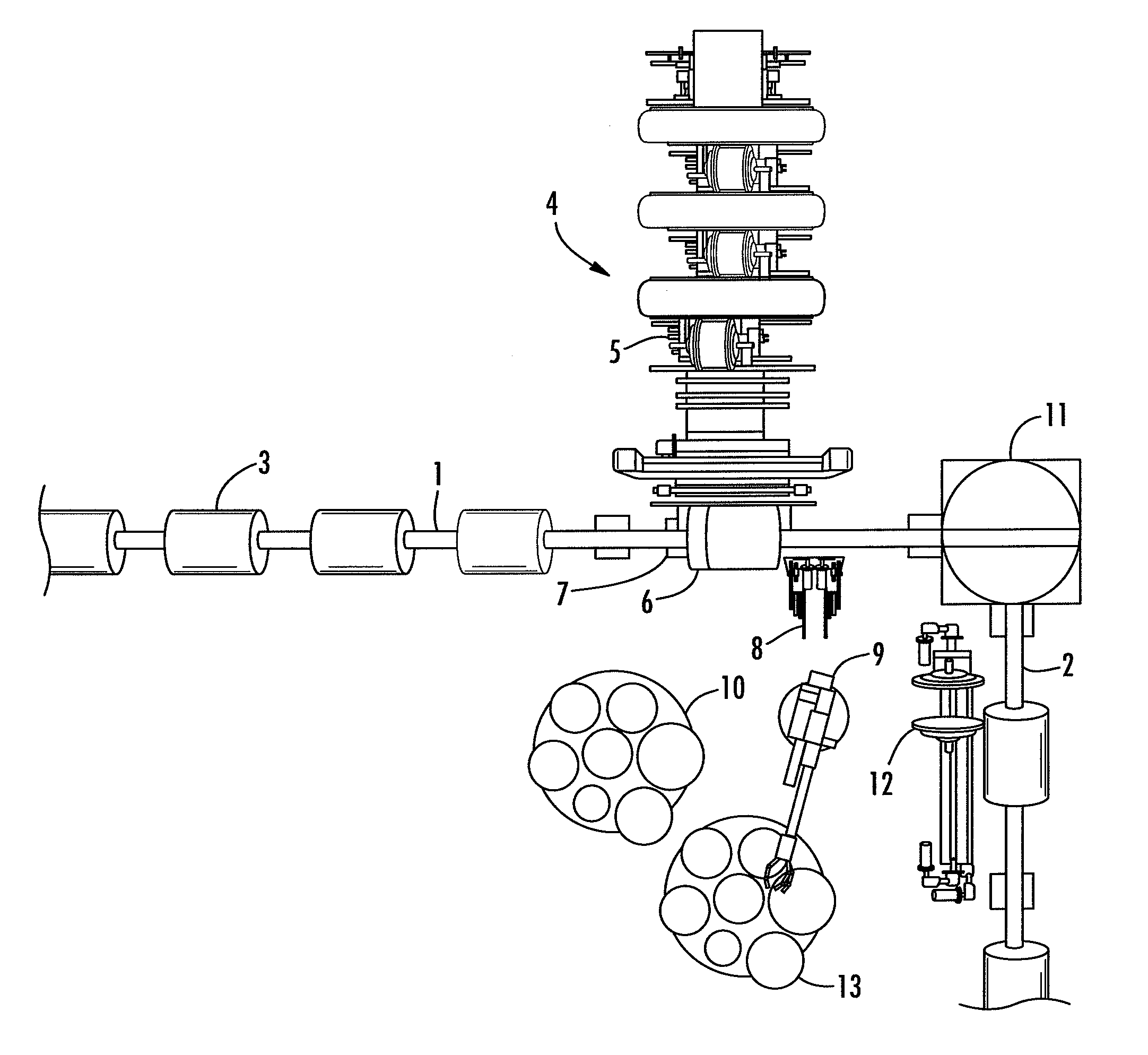
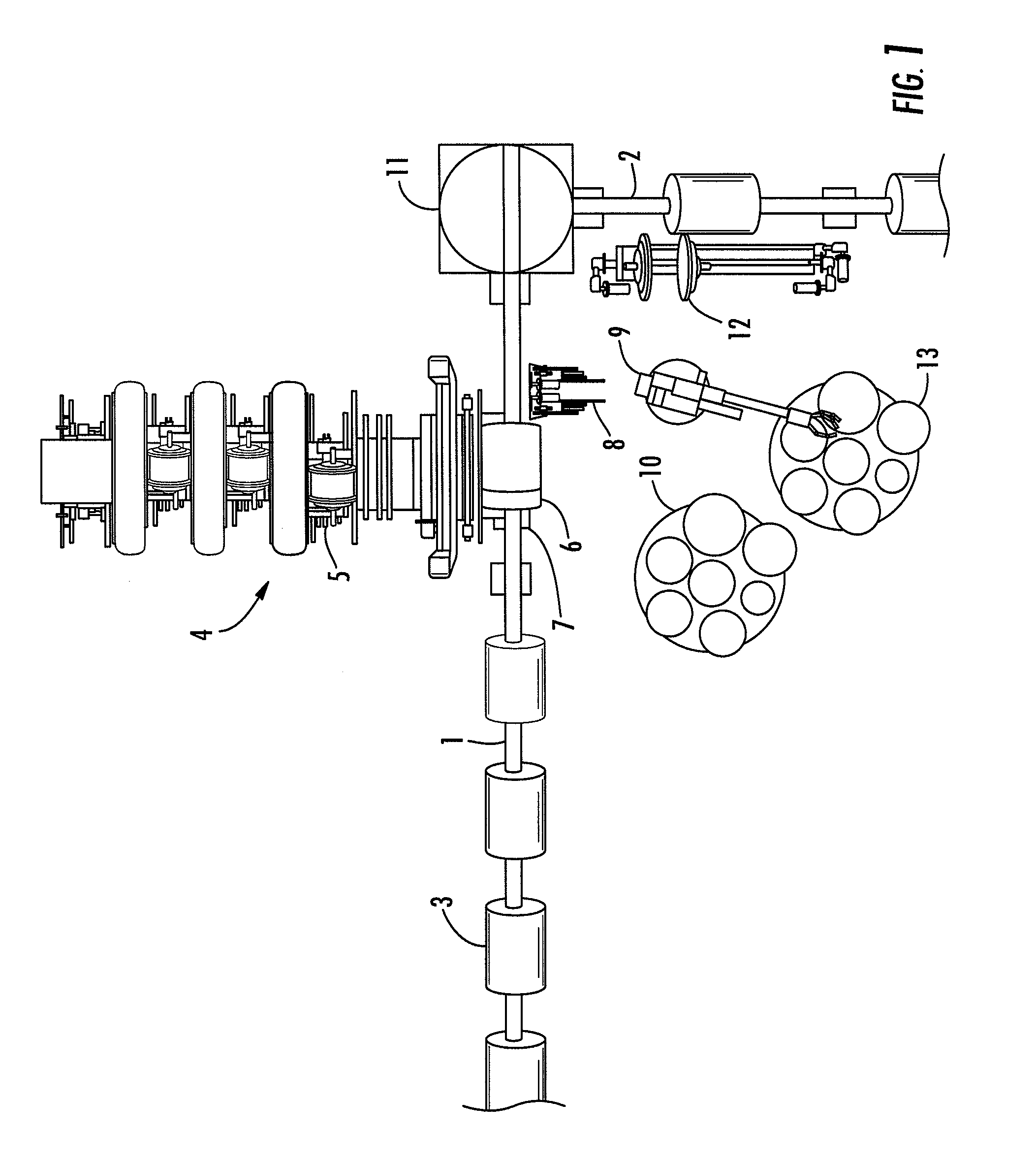
[0014]The packing system consists of a conveyor 1, 2 and reel-handing devices. The reels 3 being packed are brought to the wrapping station 4 by the first conveyor 1. The wrapping station 4 comprises, for example, several wrapping rolls 5, from which the jacket wrapping is fed to the reel 6 being packed, carrier rolls 7 for rotating the reel 6, and of course the necessary elements for controlling the movements of the wrapping 5 and the reel 6. In this case, the reel wrapping is formed from several wrapping layers wrapped parallel to each other. Other wrapping methods are spiral wrapping and wrapping with a single wide wrapping layer, which covers the reel and forms folds at the ends of the reel. Each method of wrapping has its own advantages and the present invention is suitable for use in connection with any kind of wrapping method at all. For placing the inner end shields, there are intermediate setters 8 at the wrapping station, an industrial robot 9 with several degrees of freed...


PUM

PropertyMeasurementUnit
degrees of freedomaaaaaaaaaa

Abstract

The invention relates to a method and arrangement for placing end shields on the ends of paper, pulp, or board reels (1) in connection with packing. The arrangement comprises at least one first conveyor (1) for transporting the reels (3) in a direction parallel to their axes and at least one station (4) for placing at least one inner end shield on the end of a reel (5). Next to the first conveyor (1) there are elements (8, 9) for placing an inner end shield and after the station there are elements (1) for changing the direction of the axis of the reel (5), relative to the first direction of travel, after the placing of the inner end shields, and elements for placing at least one outer end shield on the end of the reel. Further, the arrangement comprises elements (11) for making the direction of travel of the reel to deviate from the first direction of travel prior to the placing of the outer end shield, and end-shield collection stations, which are located within the operating area of one element placing the end shields, so that this element can transfer both inner and outer end shields for placing.

Description

PRIORITY CLAIM[0001]This is a national stage of application No. PCT / FI2005 / 000546, filed on Dec. 22, 2005. Priority is claimed on application No. 20041663, filed in Finland on Dec. 23, 2004.BACKGROUND OF THE INVENTION[0002]The present invention relates to a method for placing the end shields of paper, board, or pulp reels, in connection with the packaging of the reels. In the method, the reel to be packaged is brought to a wrapping station and inner end shields are first fastened to the ends of the reel and a wrapping material is wrapped on top of the surface of the jacket of the reel and outer end shields are placed on the ends, after which the reel is moved away from the wrapping station.[0003]The invention also relates to an arrangement intended to apply the method.[0004]A wide paper reel coming from a paper machine is first of all taken to a slitter-winder and cut into customer reels of a suitable width. Next, the reels are packaged for transporting. When packaging paper reels, ...

Claims


Application Information

Patent Timeline
Patent Type & Authority Patents(United States)
IPC IPC(8): B65B61/22B65B25/14B65G
CPCB65B25/148
Inventor LINDBERG, HARRI
Owner VALMET TECH INC
Why Eureka
Try Eureka