Method of moulding a wind turbine blade

a technology of wind turbine blades and moulding methods, which is applied in the manufacture of final products, manufacturing tools, other domestic articles, etc., can solve the problems of easy application of release agents, uneven or dimpled component surfaces, and health hazards to anyone exposed, so as to reduce the ability of other materials to stick, easy to remove, and easy to manufactur

Inactive Publication Date: 2015-04-14
SIEMENS GAMESA RENEWABLE ENERGY AS
View PDF19 Cites 0 Cited by
  • Summary
  • Abstract
  • Description
  • Claims
  • Application Information

AI Technical Summary

Benefits of technology

[0008]An obvious advantage of the method is that the film obviates the need for a release agent, so that it is no longer necessary to coat the inside surface (or ‘interior surface’) of the mould with a release agent, and it is no longer necessary to remove remnants of a release agent from the cured wind turbine blade. In this way, considerable savings can be made in the manufacturing process, without having to use an expensively prepared mould. Instead, a single sheet of film can simply be laid out to line the mould. After curing, the film can easily be detached from the wind turbine blade, as will be explained below.
[0015]The film used to line the mould can comprise any suitable material that does not adhere to the cured component layers, whether these comprise resin-filled fibre layers, thermosetting plastic layers, prepreg layers, etc. In a particularly preferred embodiment of the invention, therefore, the film comprises polyethylene, polypropylene, or any other suitable plastic, such as the type of film used to manufacture ‘cling-film’ or ‘cling-wrap’. One or both surfaces of the film can have non-stick properties so that the film can easily be removed from the cured wind turbine blade and / or the mould. The term ‘non-stick’ in the context of a film surface is to be understood that the surface has properties that prevent other materials from sticking to it. For example, the film can comprise a polyvinyl chloride component to reduce the ability of other materials to stick to it. The film used to line the mould can be manufactured easily in the required width, and can be supplied on a roll for convenient dispensing.
[0016]The thickness of the film may determine the smoothness of the film layer laid out on the mould. Evidently, the film should be flexible enough so that it can line the mould without any wrinkles or folds forming. On the other hand, the film should be strong enough to allow it to be pulled off the cured component. Therefore, in a preferred embodiment of the invention, the thickness of the film is at least 20 μm and at most 200 μm, more preferably at most 100 μm.
[0017]As mentioned above, it is desirable for the film to have as smooth a surface as possible, without wrinkles or folds, so that the surface of the moulded component will be correspondingly smooth also. Therefore, in a further preferred embodiment of the invention, the method comprises the step of applying a vacuum between the film and the interior surface of the mould. The vacuum can be applied by drawing air out through a nozzle positioned between the film and the inside surface of the mould. Extraction of air from between the film and the mould can ensure that the film lines the mould smoothly. The vacuum need only be applied until the film is sufficiently ‘pressed’ into the mould. Thereafter, the vacuum extraction can be stopped and the component layers can be built up in the mould. Of course, if required, the vacuum can be applied also during laying up the layers, for example to prevent slippage of the film.
[0018]The material and structure of the film used to line the mould can be chosen according to process requirements. For example, as mentioned above, it is desirable to obtain as flat a surface as possible when extracting air by vacuum from between the film and the mould. However, during vacuum extraction, it may be that the film is sucked onto the inside surface of the mould such that small air pockets are trapped. Therefore, in a particularly preferred embodiment of the invention, the film comprises a relief structure on a surface of the film applied to the inside surface of the mould. This relief structure can comprise depressions such as dimples, or raised areas, and can serve to improve the adherence of the film to the inside surface the mould during the step of laying up the component layers prior to curing. A film that lies in close contact with the inside surface of the mould is preferable in order to avoid any slippage when the component layers are laid up in the mould. Alternatively, the relief structure can comprise a plurality of channels or grooves in the film, so that a vacuum, applied between the film and the inside surface of the mould, can optimally draw out any air without allowing any significant air pockets to remain. Such channels or grooves can easily be formed during manufacture of the film, for example in an extrusion process, and are preferably arranged such that they lie in essentially the same direction as the direction taken by the extracted air, i.e. in the direction of a vacuum nozzle. In a particularly simple realisation, the film comprises parallel grooves or channels along its length, and the film is laid lengthwise into the mould, so that vacuum nozzles positioned at each end of the mould can optimally extract any air from between the film and the mould.

Problems solved by technology

However, it is not easy to apply the release agent so that these requirements are met, and the result can be an uneven or dimpled component surface.
Furthermore, the types of release agent generally used contain volatile solvents, which pose a health risk to anyone exposed to them.
However, the main disadvantage of having to use such a release agent is that, after curing, remnants of the release agent can adhere to the blade in places.
These remnants of release agent must be removed in a time-intensive procedure such as scrubbing or sandblasting, adding to the overall cost of manufacture.

Method used


Image

  • Method of moulding a wind turbine blade
  • Method of moulding a wind turbine blade
  • Method of moulding a wind turbine blade

Examples


Embodiment Construction

[0027]In the drawings, like reference numbers refer to like objects throughout. Objects in the diagrams are not necessarily drawn to scale.

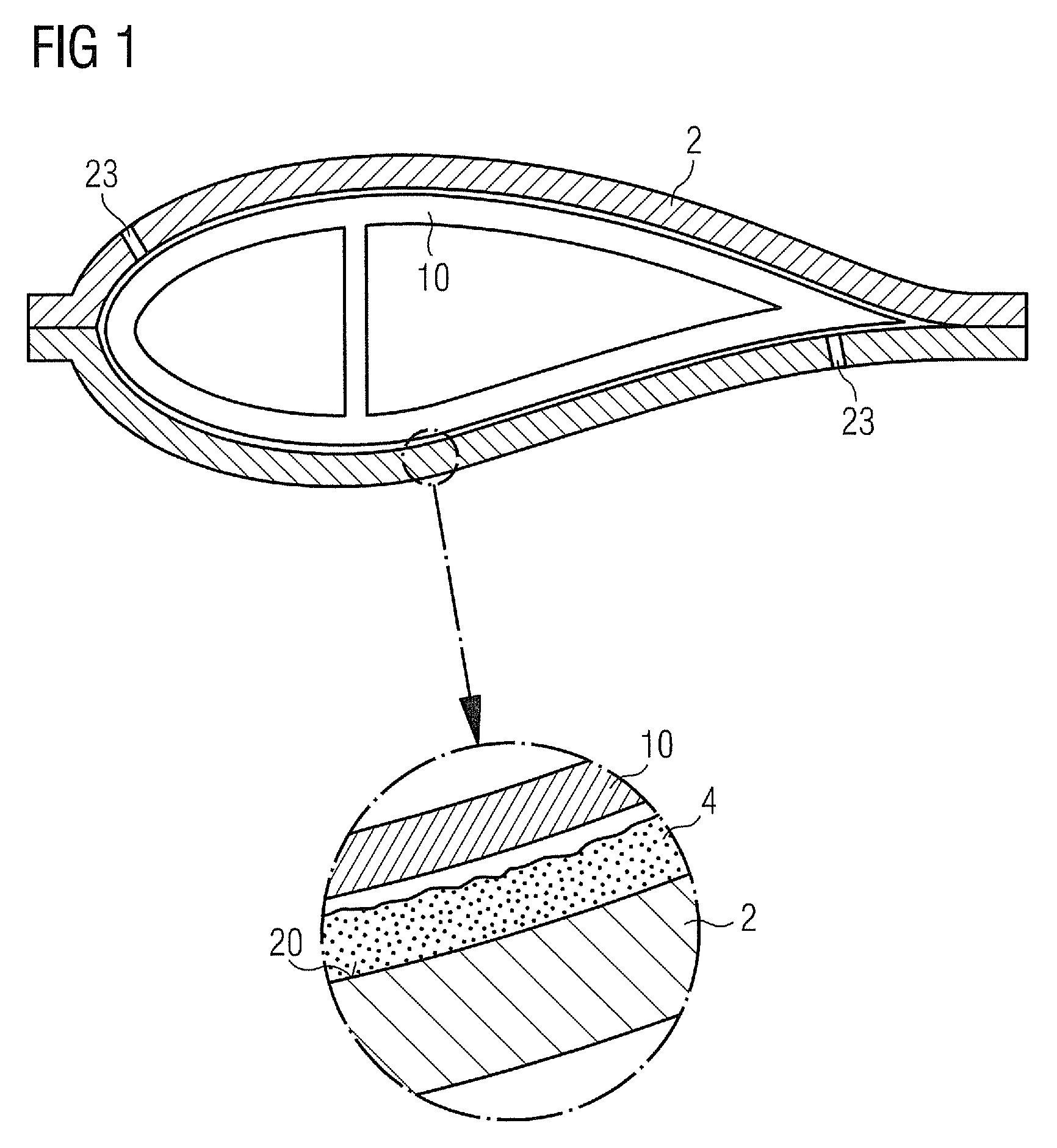
[0028]FIG. 1 shows a cross-section through a mould 2 with laid-up component layers 10 in a prior art component moulding process such as that described in EP 1 310 351 A1, in which a wind turbine blade is formed of fibre layers 10 and cured in a closed mould 2 into which resin is injected under pressure. Here, the mould 2 comprises nozzles 23 through which air can be extracted during a vacuum extraction step, thus causing the component layers 10 to expand, and by means of which glue or resin is drawn into the component layers 10. To allow the cured wind turbine blade to be removed from the mould 2 without damage to its surface, a layer of release agent 4 such as silicone wax is applied to the inside surfaces 20 of the mould 2, as shown in the enlarged part of the diagram. When removing the cured blade from the mould 2, remnants of the wax 4 can re...


PUM

PropertyMeasurementUnit
thicknessaaaaaaaaaa
thicknessaaaaaaaaaa
thicknessaaaaaaaaaa

Abstract

A method of molding a wind turbine blade in a mold is provided. The method includes applying a film to an inside surface of a mold, assembling component layers for the wind turbine blade on the film, performing curing to harden the component layers, and subsequently removing the cured wind turbine blade from the mold. Also provided is a film suitable for use in a wind turbine blade molding process and a mold suitable for molding a wind turbine blade.

Description

CROSS REFERENCE TO RELATED APPLICATIONS[0001]This application claims priority of European Patent Office application No. 10163393.1 EP filed May 20, 2010, which is incorporated by reference herein in its entirety.FIELD OF INVENTION[0002]The invention describes a method of moulding a wind turbine blade, a film for use in a wind turbine blade moulding process, and the use of such a film in the moulding of a wind turbine blade.BACKGROUND OF INVENTION[0003]Wind turbine rotor blades may be manufactured using a technique such as the closed-mould casting technique in which the entire blade can be moulded. Glass fibre matting can be used to build up component layers in a suitably shaped mould, and the layers of matting are bonded with a resin and cured in the mould to give a fibre-reinforced polymer or glass-reinforced plastic, generally referred to simply as ‘fibreglass’. Such a method is described in EP 1 310 351 A1.[0004]To facilitate releasing the finished fibreglass component after curi...

Claims


Application Information

Patent Timeline
Patent Type & Authority Patents(United States)
IPC IPC(8): B32B37/10B29C33/10B29C33/68B29C70/34B29K23/00B29L31/08
CPCB29C70/342B29C33/68B29C33/10B29K2023/06B29K2023/12B29L2031/082B29L2031/085Y02E10/721Y10T428/24479Y10T428/2457C08J2323/06C08J2323/12Y02E10/72Y02P70/50B29C39/10B29C39/42C08J5/18
Inventor SCHIBSBYE, KARSTEN
Owner SIEMENS GAMESA RENEWABLE ENERGY AS
Why Eureka
Try Eureka