Device and method for measurement of surfaces

a technology for measuring devices and surfaces, applied in the direction of instruments, lenses, optical elements, etc., can solve the problems of restricted measurement accuracy, improper function or rapid destruction, only tolerable objects, etc., and achieve the effect of strong miniaturization and free parametrization

Active Publication Date: 2009-07-14
MICRO EPSILON MESSTECHNIK GMBH & CO KG +1
View PDF8 Cites 115 Cited by
  • Summary
  • Abstract
  • Description
  • Claims
  • Application Information

AI Technical Summary

Benefits of technology

[0023]In particularly advantageous fashion, by using a GRIN lens in conjunction with additional optics, an imaging optics can be constructed that is relatively freely parametrizable and very strongly miniaturizable. Measurement heads with very small diameters can be implemented on this account.

Problems solved by technology

Burrs or waviness of the surface that can form during production of objects are only tolerable in many applications in very narrow limits.
Especially in high-precision mechanisms with moving parts, insufficient surface quality can lead to improper function or rapid destruction.
However, only very restricted measurement accuracies can be achieved with such measurement systems.
In this way, the surface can be measured relatively precisely, but the measurement speed is severely restricted because of necessary adjustment of the optics.
Measurement of the surface in a running production process is therefore not feasible.
Relatively large measurement speeds can be achieved, but the spacing between the optics and the measurement object is subject to very sharp restrictions.
If lenses with a larger focal length are used, larger measurement spacings and measurement areas can be achieved, but the measurement accuracy or resolution of the arrangement significantly diminishes.

Method used


Image

  • Device and method for measurement of surfaces
  • Device and method for measurement of surfaces
  • Device and method for measurement of surfaces

Examples


Embodiment Construction

[0030]The present invention now will be described more fully hereinafter with reference to the accompanying drawings, in which some, but not all embodiments of the invention are shown. Indeed, the present invention may be embodied in many different forms and should not be construed as limited to the embodiments set forth herein; rather, these embodiments are provided so that this disclosure will satisfy applicable legal requirements. Like numbers refer to like elements throughout.

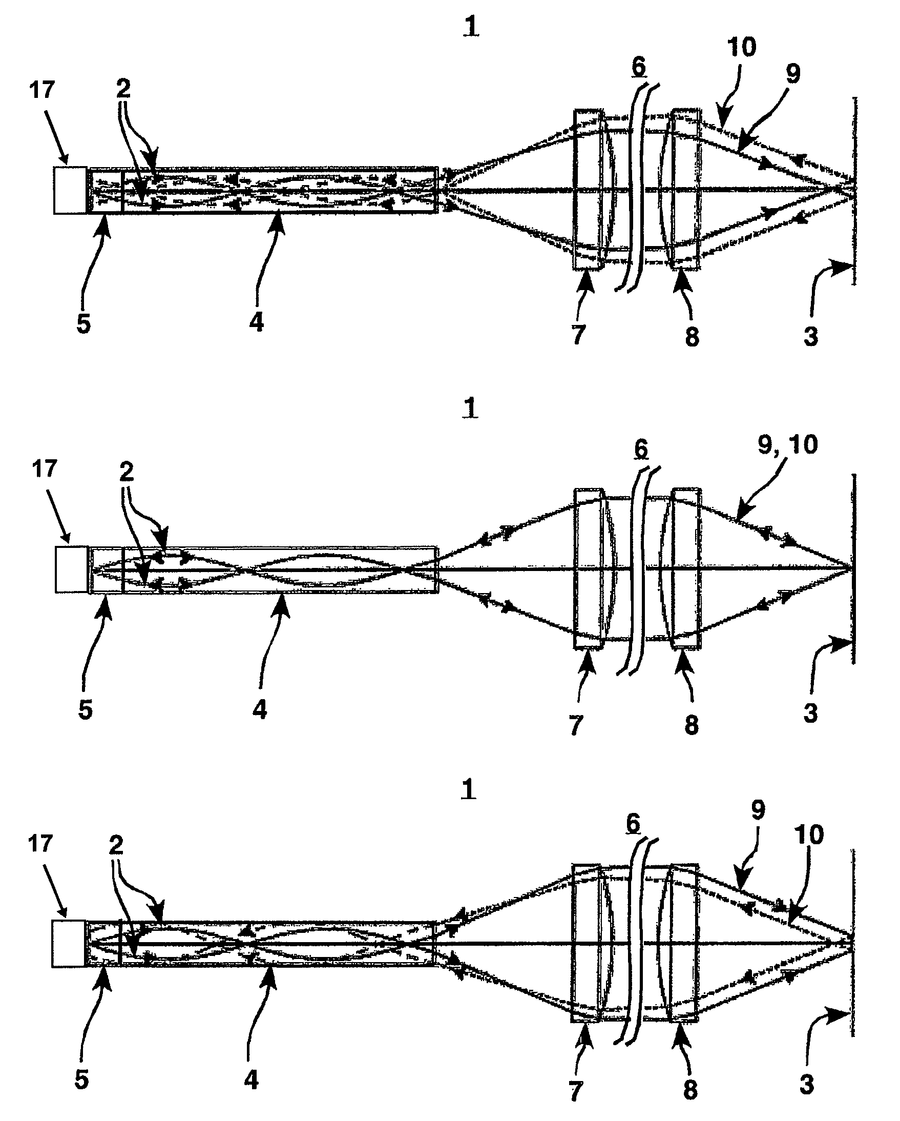
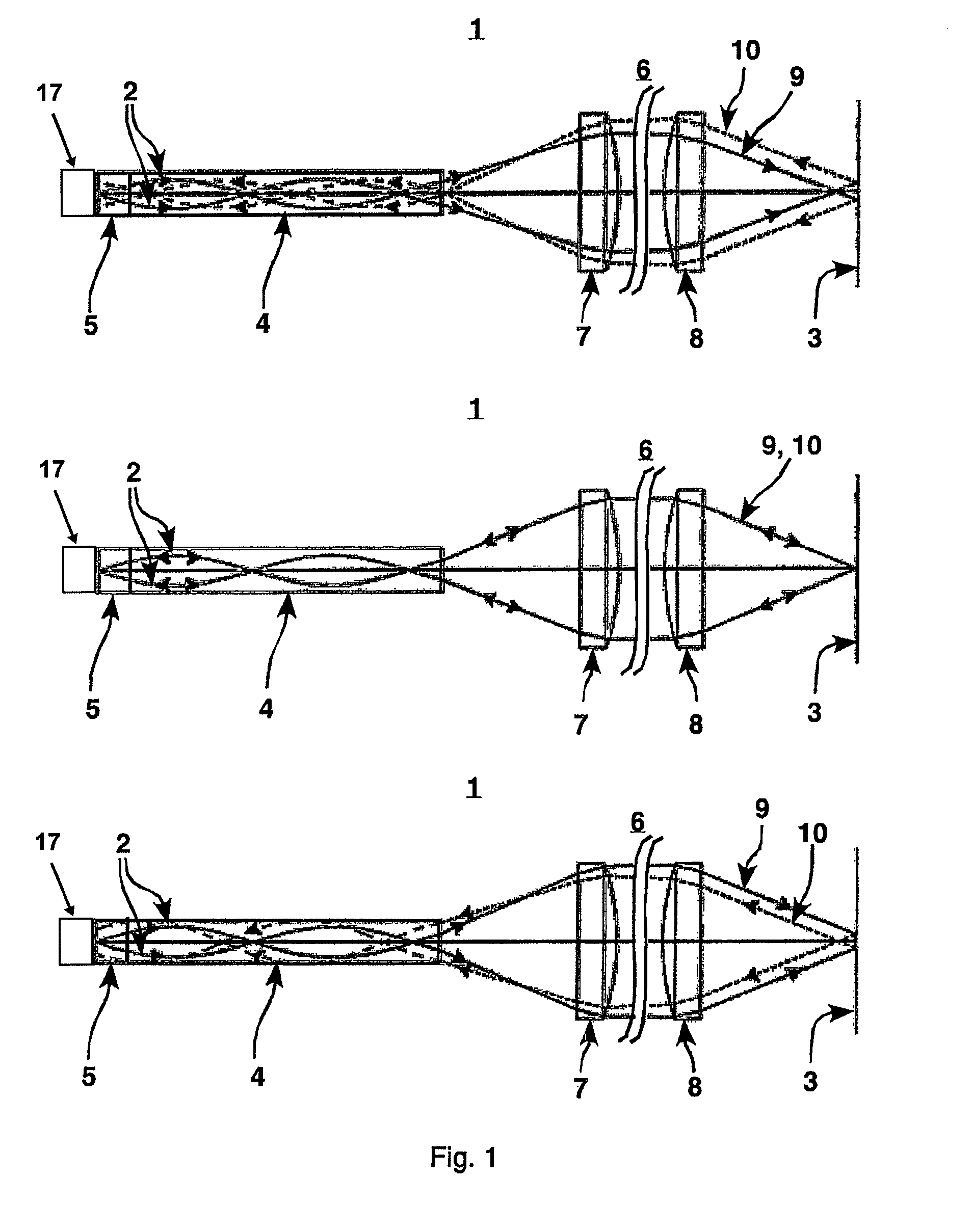
[0031]The beam path of a multicolor light beam 2 through the imaging optics 1 according to the invention is shown in FIG. 1. The upper part of the figure shows the preparation of a short-wave fraction of light beam 2, whereas the beam path of a long-wave fraction is shown in the lower part of the figure. In the middle part, the spectral fraction of the light beam 2 is shown, which is focused exactly on surface 3, and whose wavelength therefore assumes a value that lies between the values of the fractions sh...


PUM

PropertyMeasurementUnit
distancesaaaaaaaaaa
chromatic aberrationaaaaaaaaaa
lengthaaaaaaaaaa

Abstract

The invention relates to a device for measuring surfaces and to a method, which uses, preferably, the device. The device comprises a light source which is used to produce a multi-colored light beam. The light beam can be focused by an imaging optical system on a plurality of points which are arranged at different distances from the imaging optical system, using the chromatic aberration of the optics. The focused light beam can be deviated to a point of the surface. A sensor device is provided in order to detect the reflected light beam. The aim of the invention is to maintain the largest distance possible between the measuring head and the object. The imaging optical system comprises an optical system for the targeted circulation of a chromatic aberration and an additional optical system which is used to form the focused light beam emerging from the imaging optical system.

Description

CROSS REFERENCE TO RELATED APPLICATION[0001]The present application is a continuation of international application PCT / DE2006 / 000800, filed 10 May 2006, and which designates the U.S. The disclosure of the referenced application is incorporated herein by reference.BACKGROUND OF THE INVENTION[0002]The invention concerns a device for measurement of surfaces and a method for operation of a device, in which the device has a light source to generate a multicolor light beam, the light beam being focusable by imaging optics, using chromatic aberration of the optics, on several points at different distance from the imaging optics, in which the focused light beam can be controlled on the surface and a sensor device is provided to detect the reflected light beam.[0003]In many areas of engineering it is important to have precise knowledge concerning the condition of surfaces. Burrs or waviness of the surface that can form during production of objects are only tolerable in many applications in v...

Claims


Application Information

Patent Timeline
Patent Type & Authority Patents(United States)
IPC IPC(8): G01N21/55
CPCG01B11/24G02B21/0064G01B2210/50
Inventor STAUTMEISTER, TORSTENMESSERSCHMIDT, BERNHARDWISSPEINTER, KARL
Owner MICRO EPSILON MESSTECHNIK GMBH & CO KG
Why Eureka
Try Eureka