Orthodontic device and method for treating malocclusions

a technology of orthodontic devices and malocclusions, applied in the field of orthodontic appliances, can solve the problems of increasing the size and complexity of the inventory, the complex connection between a spring-biased bite corrector and the upper and lower arches, and the drawbacks of the current orthodontic device for the treatmen

Inactive Publication Date: 2009-08-25
ORMCO CORP
View PDF66 Cites 31 Cited by
  • Summary
  • Abstract
  • Description
  • Claims
  • Application Information

AI Technical Summary

Problems solved by technology

While Herbst devices are generally successful for moving the jaws over a significant distance and in a relatively short period of time, it is sometimes necessary to follow treatment using a Herbst device with treatment using a spring-biased bite corrector.
The connection between a spring-biased bite corrector and the upper and lower arches is typically complex, utilizing multiple separate parts.
In any event, there are some drawbacks to the current orthodontic devices for the treatment of malocclusions as described above.
The different approaches and devices for treating a malocclusion, i.e., Herbst device or spring-biased bite corrector, requires a physician to store multiple devices having multiple, separate parts, which increases the size and complexity of inventory.
This can be a time consuming and therefore a costly process.
In addition to the above, another drawback is that connections that pivotally couple the Herbst device or the spring-biased bite corrector to the upper and lower arches require assembling multiple separate pieces, which may be difficult and time consuming.
This may be particularly true if the device is coupled to a molar in the posterior of the mouth and therefore having limited accessibility.
Moreover, in order to maintain the pivotal connection and withstand the forces exerted during orthodontic treatment, the connectors that couple the device to the teeth, as well as the tools used to make the connection, are often large and bulky.
These components and associated tools may therefore cause patient discomfort through contact with oral tissues.
In yet another drawback, current connectors, and especially screw-based connectors, provide very limited movement of the jaws in a lateral direction (i.e., left to right movements).
This leads to increased device breakage, as patients attempt to move their jaws in the lateral direction, and is generally uncomfortable for the patient.

Method used


Image

  • Orthodontic device and method for treating malocclusions
  • Orthodontic device and method for treating malocclusions
  • Orthodontic device and method for treating malocclusions

Examples


Embodiment Construction

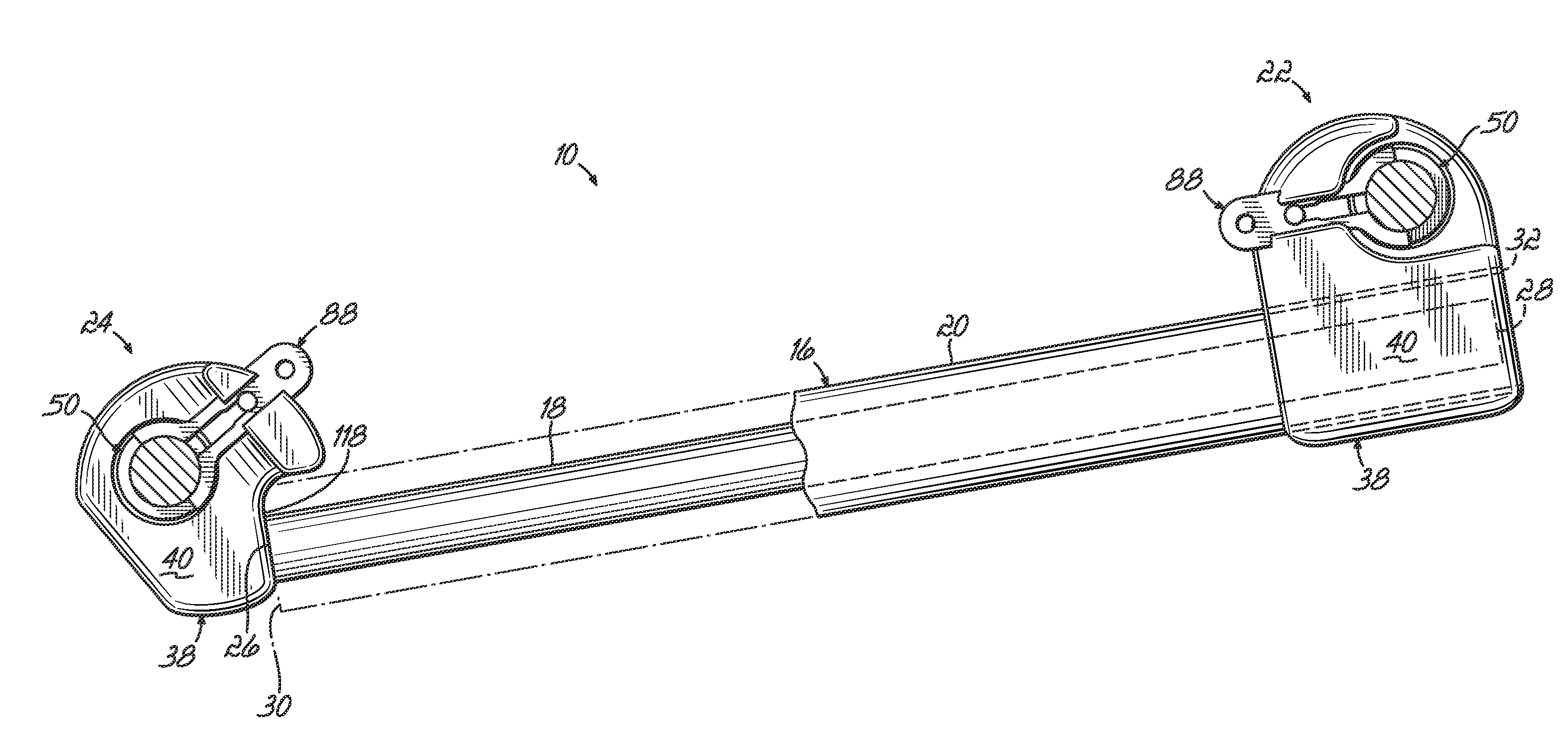
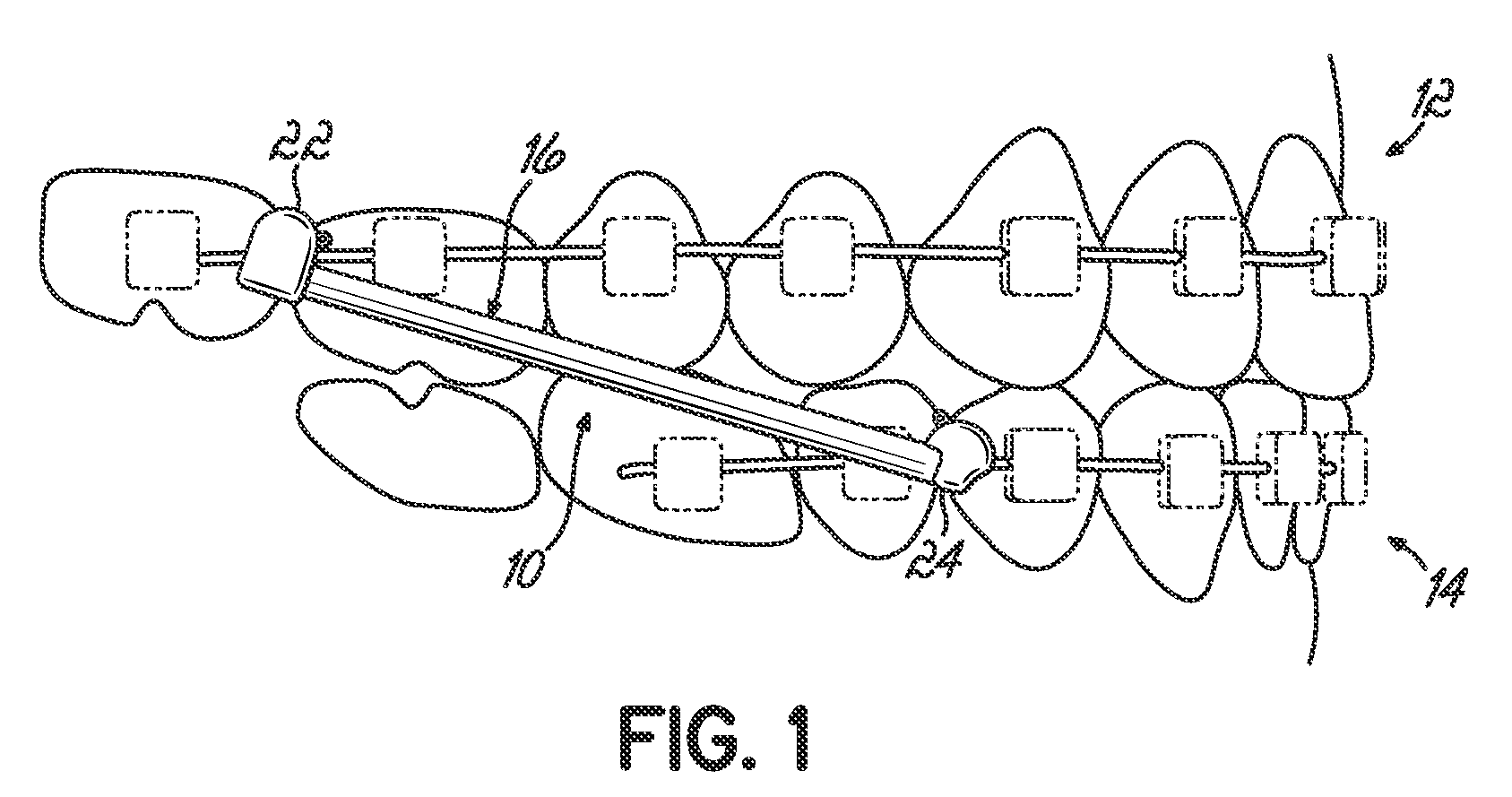
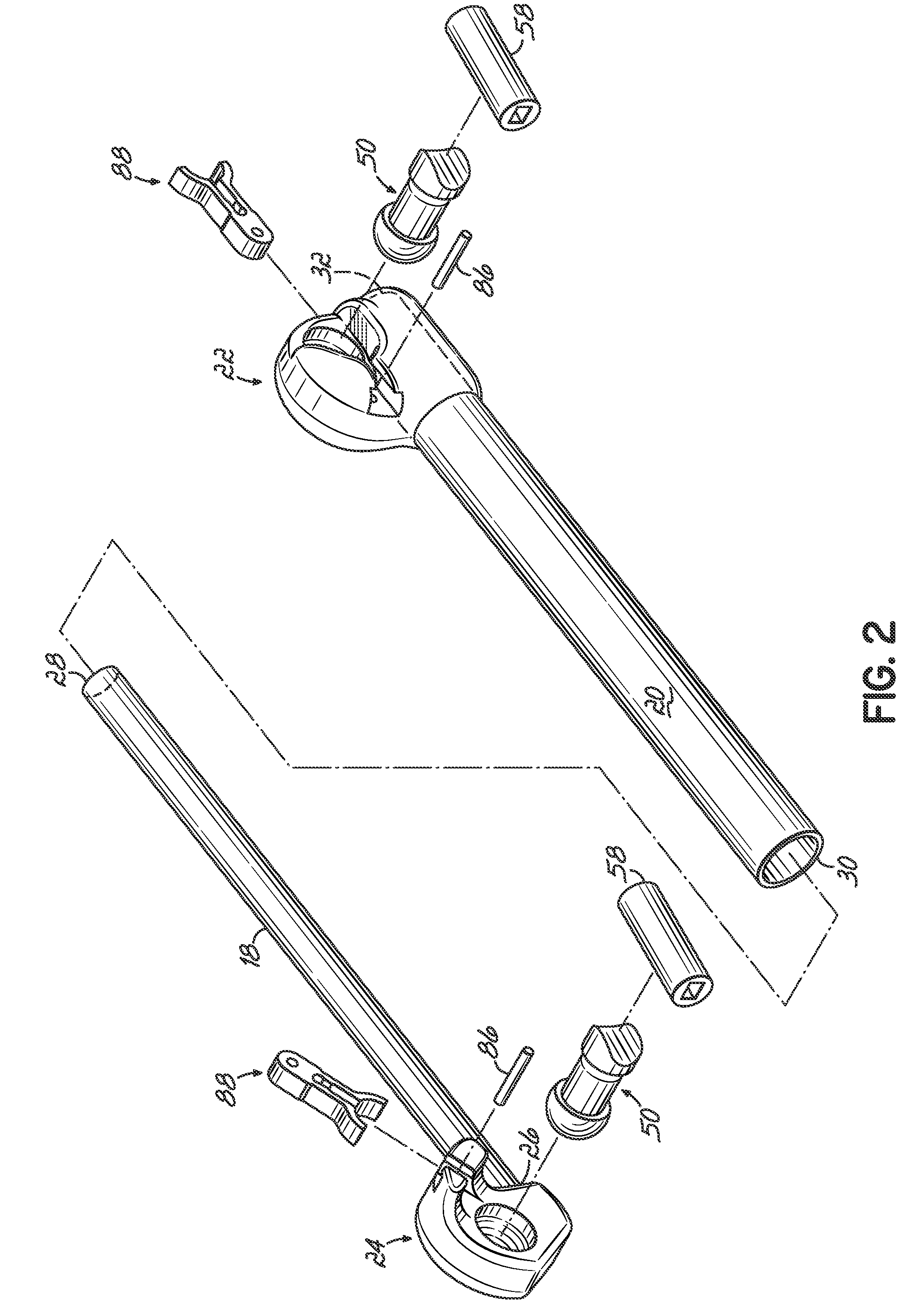
[0048]Referring to FIGS. 1-4, an orthodontic device 10 according to one embodiment of the invention may be coupled to the upper dental arch, or maxillary jaw 12, and the lower dental arch, or mandibular jaw 14, so as to reposition the mandibular jaw 14 relative to the maxillary jaw 12 and therefore correct a malocclusion, such as a Class II malocclusion. The orthodontic device 10 includes a telescoping rod assembly 16, comprising an inner rod 18 and an outer sleeve 20, and upper and lower connecting devices 22, 24, respectively.

[0049]The inner rod 18 includes a first end 26 and a second opposed end 28. The first end 26 of inner rod 18 is coupled to the lower connecting device 24. In a similar manner, outer sleeve 20 includes a first end 30 and a second opposed end 32. The second end 32 of the outer sleeve 20 is coupled to the upper connecting device 22. The inner rod 18 is configured to fit within the outer sleeve 20 to provide the telescoping feature of the assembly 16. To this end...


PUM


Abstract

A dental apparatus for use with a connecting member coupled to a jaw in a patient's mouth. The apparatus includes an orthodontic device and a connecting device carried by the orthodontic device. The connecting device includes a receptacle adapted to partially receive the connecting member and a blocking member. The blocking member is moveable relative to the receptacle between an opened position in which the connecting member may be disengaged from the receptacle and a closed position in which the connecting member is captured within the receptacle for pivotally engaging the orthodontic device with the connecting member. The orthodontic device may further include a biasing member selectively activated to provide a spring-biased force to the jaw. A method of using the dental apparatus includes moving the blocking member to capture / release the connecting member in the receptacle and activating / deactivating the biasing member to operate the apparatus in a different mode.

Description

CROSS REFERENCE TO RELATED APPLICATION[0001]This application claims priority to provisional patent application Ser. No. 60 / 757,944 filed on Jan. 11, 2006, the disclosure of which is expressly incorporated by reference herein in its entirety.FIELD OF THE INVENTION[0002]The present invention relates generally orthodontic appliances, and more particularly to an orthodontic device and methods for treating malocclusions.BACKGROUND OF THE INVENTION[0003]Orthodontic treatment involves movement of malpositioned teeth to orthodontically correct positions. During treatment, small orthodontic appliances known as brackets are often coupled to anterior, bicuspid, and molar teeth, and an archwire is placed in a slot of each bracket. The archwire forms a track to guide movement of the brackets and the associated teeth to desired positions for correct occlusion. Typically, the ends of the archwire are held by appliances known as buccal tubes that are secured to a patient's molar teeth. The brackets...

Claims


Application Information

Patent Timeline
Patent Type & Authority Patents(United States)
IPC IPC(8): A61C3/00
CPCA61C7/36
Inventor SHEIKH, HAMIDDAMON, DWIGHTCORCORAN, KEVIN
Owner ORMCO CORP
Why Eureka
Try Eureka