Multi-layer resonator for magnetic resonance applications with circuitry allowing equal magnitude current during active operation

a magnetic resonance and circuitry technology, applied in the field of magnetic resonance resonance applications, can solve the problems of inability to achieve, significant technical expenditure, unrealistic length of magnetic resonance resonances,

Inactive Publication Date: 2009-08-25
SIEMENS HEALTHCARE GMBH
View PDF13 Cites 83 Cited by
  • Summary
  • Abstract
  • Description
  • Claims
  • Application Information

AI Technical Summary

Benefits of technology

[0017]Due to the fashioning of the conductor element as a multi-layer conductor, the possibility exists for the first time to distinctly reduce the effective resistance of the conductor element relative to a solid conductor. Due to the formation of the circuit that effects the uniform current distribution into the individual layers, this possibility is then actually enabled to be utilized.

Problems solved by technology

As results from a simple calculation, the length of a λ / 2 rod is thus approximately 2.5 m for a magnetic resonance system with a basic magnetic field of 1.5 T. Such lengths are unrealistic for resonators for use in magnetic resonance applications.
For this reason, for resonators for magnetic resonance applications it is not possible without further measures to achieve tuning to the Larmor frequency by dimensioning of the conductor element.
These procedures, however, would involve a significant technical expenditure and moreover represent a safety risk for a patient who is examined in the magnetic resonance system.
However, the use of multi-layer conductors as conductor elements does not lead to the expected reduction of the effective resistance without further measures.
More precise tests have shown that the problem is that the optimal distribution of the resonance current among the individual layers of the multi-layer conductor after a transition from a solid (non-layered) conductor or an external circuit to the multi-layer conductor ensues only after a length that is greater than the wavelength corresponding to the resonance frequency.
Moreover, slight inhomogeneities of the multi-layer conductor lead to a significant reduction of the achievable resistance decrease.
The use of multi-layer conductors in resonators in resonators for magnetic resonance applications has conventionally not been thought to be reasonable in practice.

Method used


Image

  • Multi-layer resonator for magnetic resonance applications with circuitry allowing equal magnitude current during active operation
  • Multi-layer resonator for magnetic resonance applications with circuitry allowing equal magnitude current during active operation
  • Multi-layer resonator for magnetic resonance applications with circuitry allowing equal magnitude current during active operation

Examples


Embodiment Construction

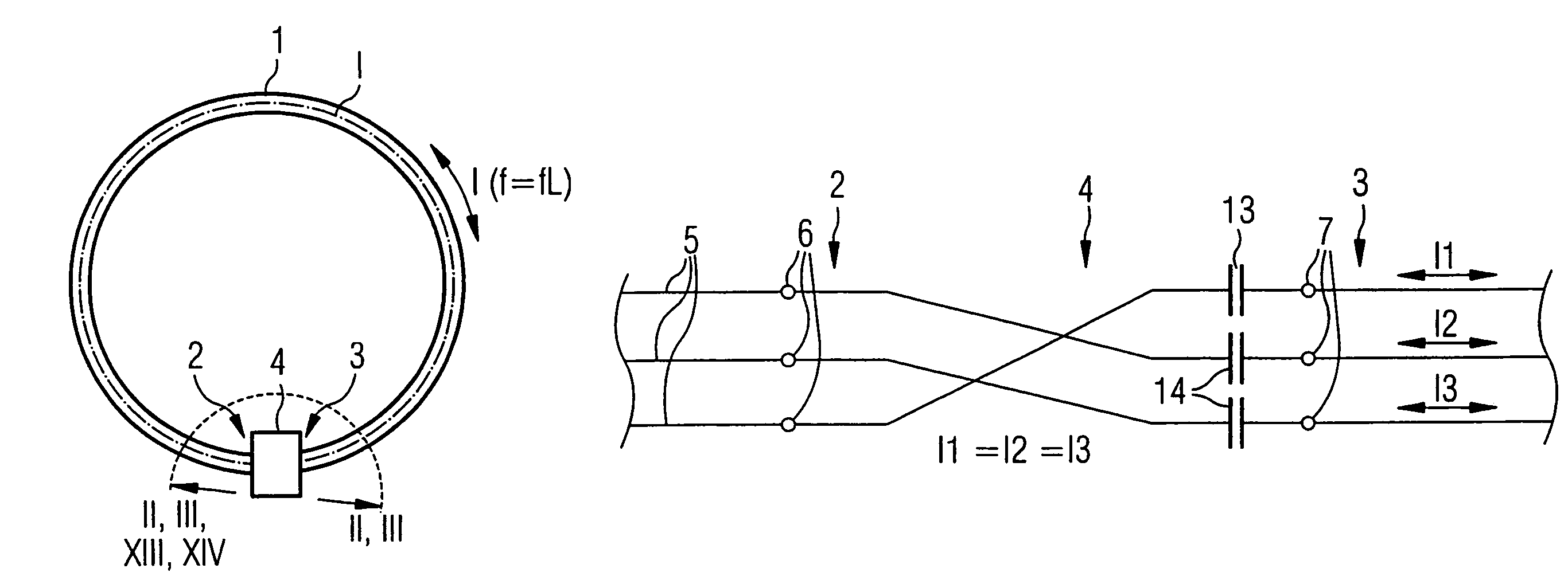
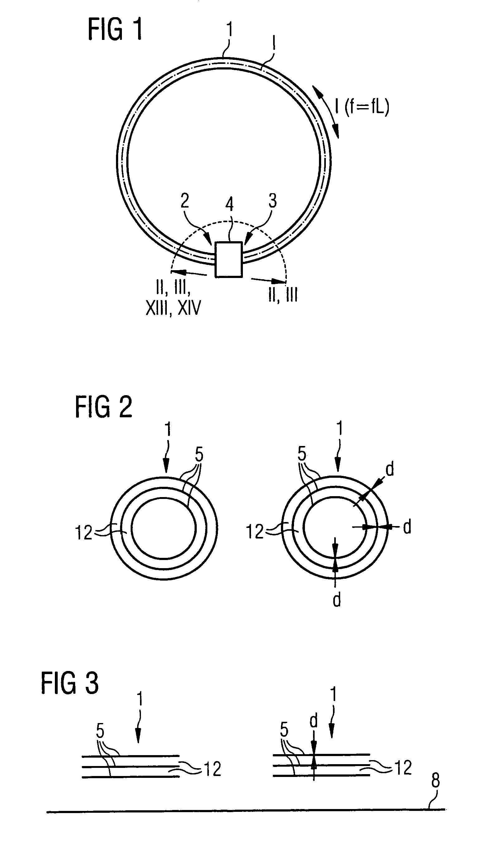
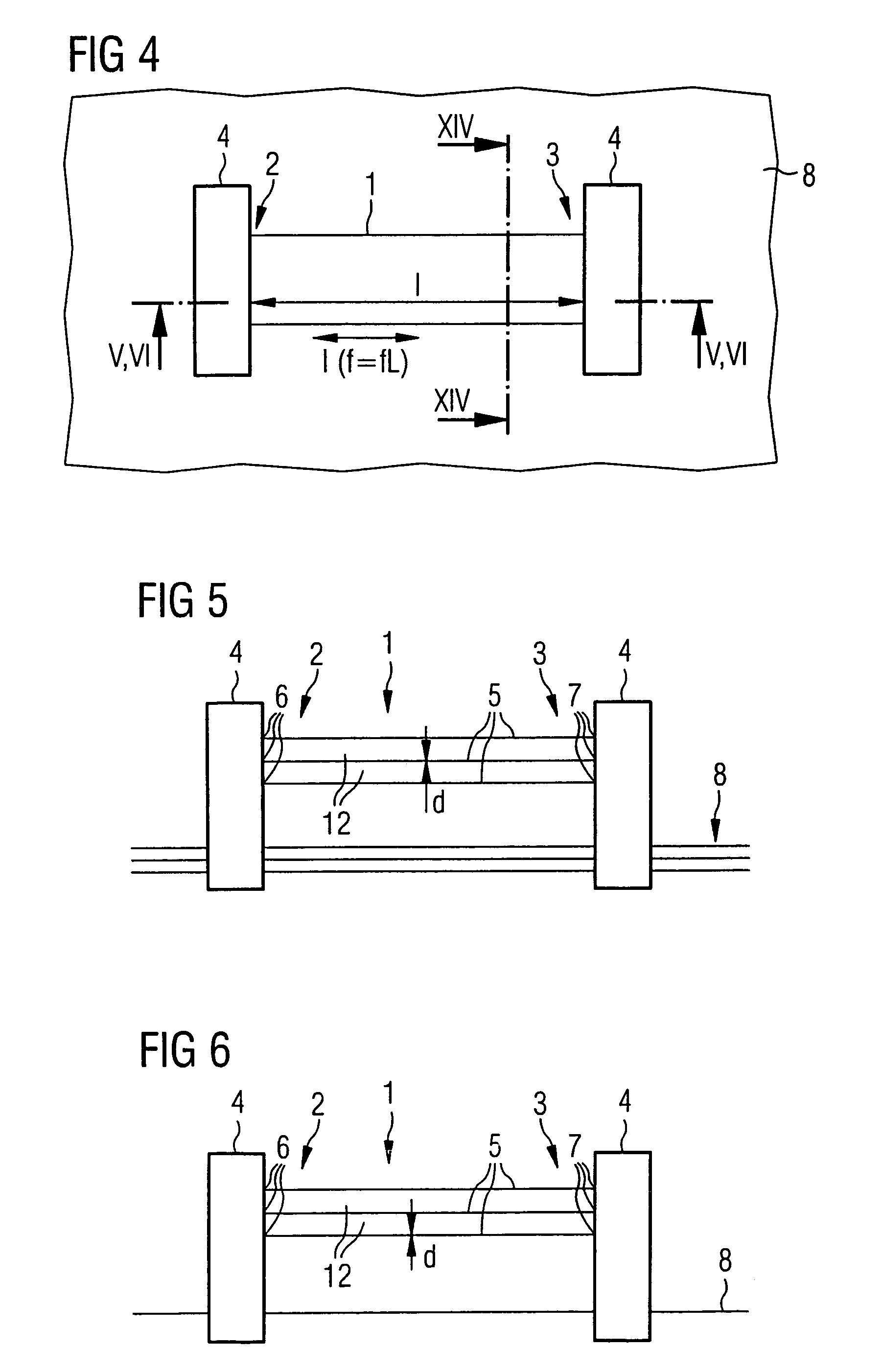
[0036]According to FIG. 1, a resonator for magnetic resonance applications has a conductor element 1 that extends from a first conductor end 2 to a second conductor end 3. During operation of the conductor element 1, a resonance current I oscillates with a resonance frequency f in the conductor element 1 from the first conductor end 2 to the second conductor end 3 and back.

[0037]In magnetic resonance applications the resonance frequency f corresponds with the Larmor frequency fL of a magnetic resonance system. The conductor element 1 therefore extends over a length l that is significantly smaller than half of the wavelength corresponding with the resonance frequency f. The conductor ends 2, 3 are coupled with one another via a circuit 4, whereby the conductor element 1 is tuned to the resonance frequency f by the circuit 4.

[0038]The conductor element 1 of FIG. 1 forms essentially an annular shape. It is therefore possible for the circuit 4 to directly couple the two conductor ends 2...


PUM


Abstract

A resonator for magnetic resonance applications has a conductor element that extends from a first conductor end to a second conductor end. During operation of the conductor element at a resonance frequency, a resonance current-oscillates from the first conductor end to the second conductor end and back. The conductor ends are coupled with one another via a circuit that tunes the conductor element to the resonance frequency. The conductor element is fashioned as a multi-layer conductor with a number of layers that have first and second layer ends at the conductor ends. The circuit causes layer currents that are of equal magnitudes to flow in the layers themselves during active operation of the conductor element at the resonance frequency.

Description

BACKGROUND OF THE INVENTION[0001]1. Field of the Invention[0002]The present invention concerns a resonator for magnetic resonance applications, the resonator being of the type having a conductor element that extends from a first conductor end to a second conductor end.[0003]2. Description of the Prior Art[0004]Resonators of the above type are generally known, for example, from DE 103 14 215 A1 (corresponding to U.S. Pat. No. 6,943,551 B). During operation of the conductor element, a resonator current oscillates at a resonator frequency in the conductor element from the first conductor end to the second conductor end and back. The conductor element is tuned to the resonance frequency by a corresponding circuit. In DE 103 14 215 A1 the conductor element is an antenna rod of a birdcage resonator that has further antenna rods, ferrules, ring conductors running axially, centrally around the birdcage resonator and connection lines to the ring conductors. The elements cited above can be co...

Claims


Application Information

Patent Timeline
Patent Type & Authority Patents(United States)
IPC IPC(8): G01V3/00H01P7/08
CPCG01R33/34G01R33/341H01P7/08H01P7/00
Inventor SCHNELL, WILFRIEDVESTER, MARKUS
Owner SIEMENS HEALTHCARE GMBH
Why Eureka
Try Eureka