Reliable cage rotor
What is Al technical title?
Al technical title is built by PatSnap Al team. It summarizes the technical point description of the patent document.
A rotor and cage-shaped technology, applied in the field of cage-shaped rotors, can solve problems such as crack formation
Active Publication Date: 2017-10-31
SIEMENS AG
View PDF2 Cites 0 Cited by
Summary
Abstract
Description
Claims
Application Information
AI Technical Summary
This helps you quickly interpret patents by identifying the three key elements:
Problems solved by technology
Method used
Benefits of technology
Problems solved by technology
There the problem of the tendency for cracks to form at the transition between the short-circuit ring and the rotor rod to occur during the one-piece production of the rotor rod and the short-circuit ring by the aluminum die-casting process is solved
Method used
Image
Click on the blue label to locate the original text in one second.
Reading with bidirectional positioning of images and text.
Examples
Embodiment Construction
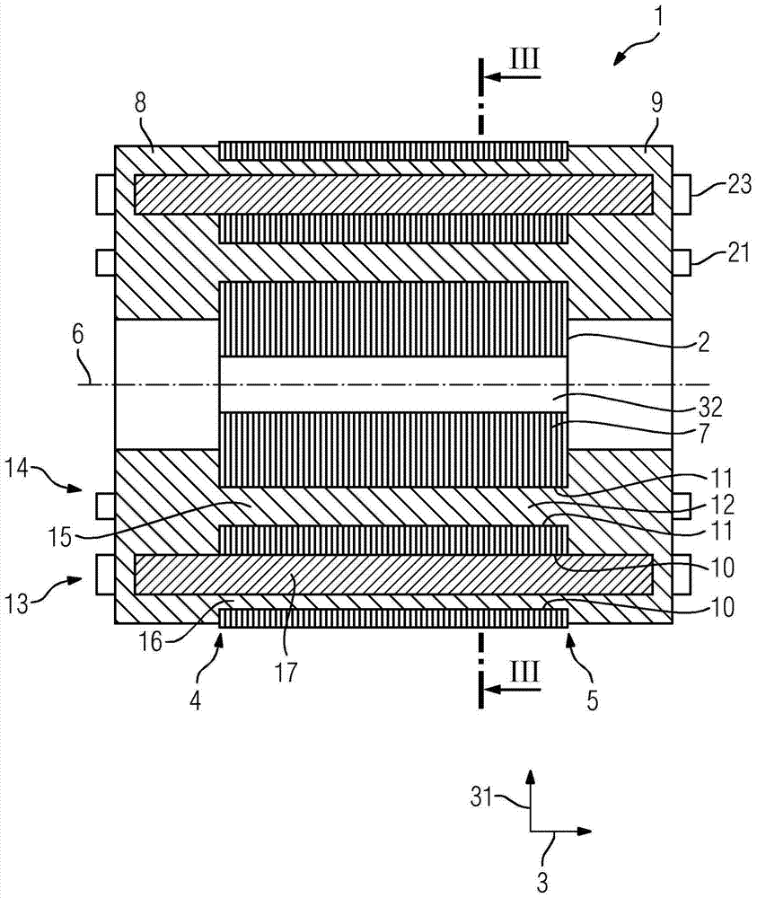
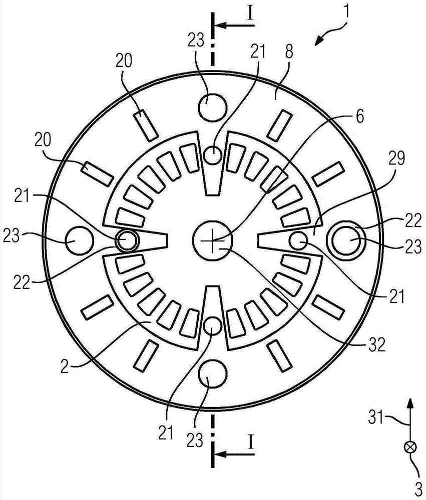
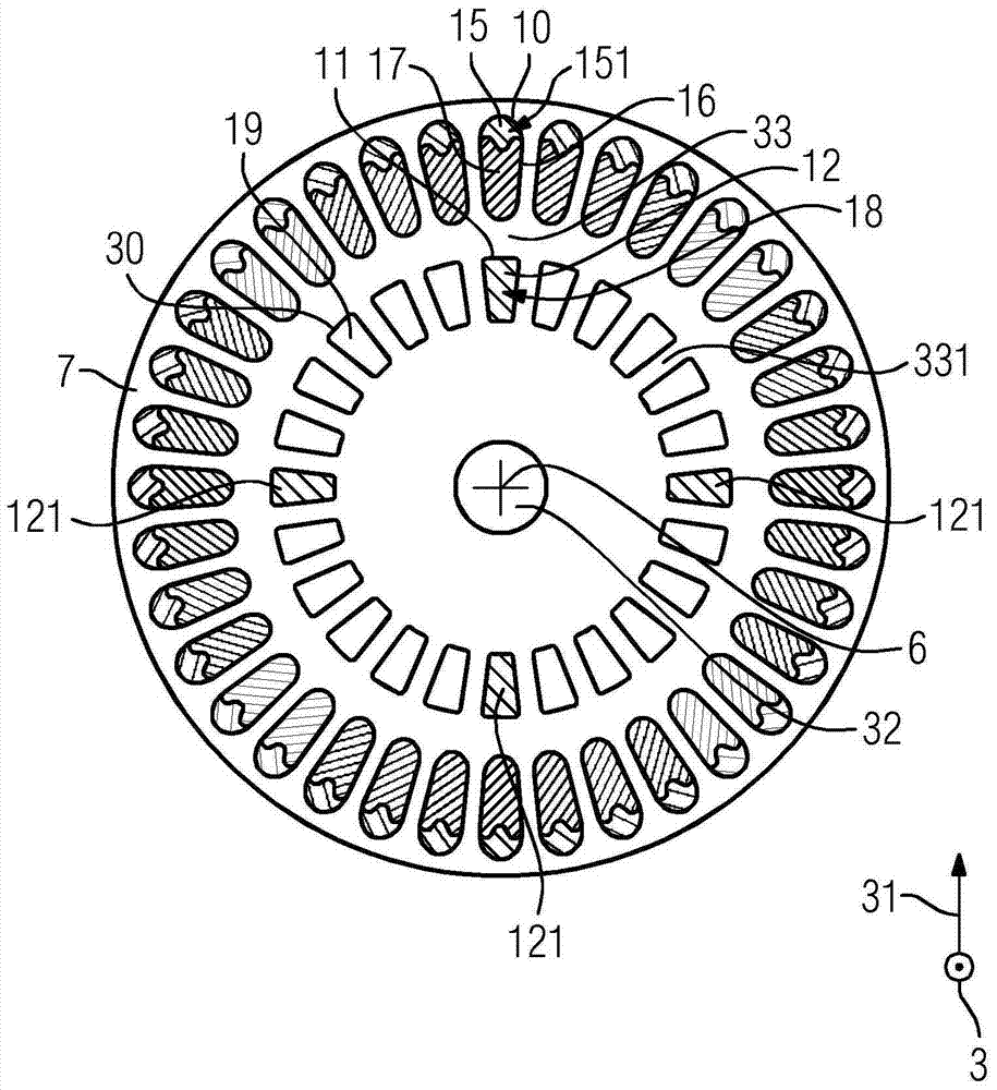
[0071] figure 1 An embodiment of a cage rotor 1 is shown, comprising a rotor plate stack 2 extending in the axial direction 3 from a first axial end 4 along the axis of rotation to a second axial end 5 and having a Lamination 7 layered in axial direction 3 . The cage rotor 1 also has a short-circuit ring 8 which surrounds the axis of rotation 6 and is arranged at the first axial end 4 , and a further short-circuit ring 9 which surrounds the axis of rotation 6 and is arranged at the second axial end Part 9 on. The short-circuit ring 8 and the further short-circuit ring 9 comprise the first material. The first material is suitable for manufacturing a cage rotor by die casting and comprises aluminum in this exemplary embodiment. The laminations 7 of the rotor lamination stack 2 each have a first punching 10 which forms the edge of a groove 16 of the rotor lamination stack which extends from the first axial end 4 to the second axial end 4 . End 5. The laminations 7 also each ...
PUM
Abstract
The invention relates to a cage rotor (1, 62, 72, 82) for an electrical machine (50, 52, 54, 56), comprising: a rotor stack (2, 206, 207, 208) along The axis of rotation (6) extends in the axial direction (3) from the first axial end (4, 163, 173, 183) to the second axial end (5, 164, 174, 184) and has a a lamination (7) layered in the axial direction (3); a short-circuit ring (8) which surrounds the axis of rotation (6) and which is arranged on the first axial end (4, 163, 173, 183); and A further short-circuit ring (9) which surrounds the axis of rotation (6) and which is arranged on the second axial end (5, 164, 174, 184), wherein the short-circuit ring (8) and the further short-circuit ring (9) Comprising a first material, wherein the laminations (7) each have a first stamping (10) forming the edge of a slot (16) of a rotor plate stack (2, 206, 207, 208) from the first The axial ends (4, 163, 173, 183) extend to a second axial end (5, 164, 174, 184), wherein the laminations (7) each have a second punching (11), which Forms the edge of a channel (12, 126) extending from a first axial end (4, 163, 173, 183) to a second axial end (5, 164, 174, 184), wherein the first punch The punched part (10) is located in the outer region (13) of the laminate (7) and the second punched part (11) is located in the inner region of the laminate (7), the channel (12, 126) is made of the first material The filling material (15) is filled, and the filling material is integrally connected with the short-circuit ring (8) and the other short-circuit ring (9). The invention relates to a motor comprising a cage rotor (1, 62, 72, 82), Method for manufacturing cage rotors (1, 62, 72, 82), and sets (60, 70, 80) of electric machines (51, 52, 53, 54, 55, 56).
Description
technical field [0001] The invention relates to a cage rotor, an electric machine comprising the cage rotor, and a set of electric machines comprising at least one first electric machine with a cage rotor. Furthermore, the invention relates to a method for producing a cage rotor. Background technique [0002] Such a cage rotor is known from DE 199 01 195 A1. There, the problem of the tendency for cracks to form at the transition between the short-circuit ring and the rotor rod to occur during the one-piece production of the rotor rod and the short-circuit ring by the aluminum die-casting process is solved. To solve this problem, spacer elements are cast into the die-cast cage windings at the left and right ends between the rotor lamination and the short-circuit ring. In DE 199 01 195 A1, the problem of the lack of ventilation of the rotor is also solved in that the laminations of the rotor lamination have cooling holes for forming cooling channels extending axially through...
Claims
Application Information
Patent Timeline
Application Date:The date an application was filed.
Publication Date:The date a patent or application was officially published.
First Publication Date:The earliest publication date of a patent with the same application number.
Issue Date:Publication date of the patent grant document.
PCT Entry Date:The Entry date of PCT National Phase.
Estimated Expiry Date:The statutory expiry date of a patent right according to the Patent Law, and it is the longest term of protection that the patent right can achieve without the termination of the patent right due to other reasons(Term extension factor has been taken into account ).
Invalid Date:Actual expiry date is based on effective date or publication date of legal transaction data of invalid patent.