Inverse method to calculate material properties using an insertion loss test
a technology of insertion loss and inverse method, applied in the direction of fluid tightness measurement, vibration measurement in solids, electrical/magnetic measurement arrangement, etc., can solve problems such as practical limitations
- Summary
- Abstract
- Description
- Claims
- Application Information
AI Technical Summary
Benefits of technology
Problems solved by technology
Method used
Image

Examples
Embodiment Construction
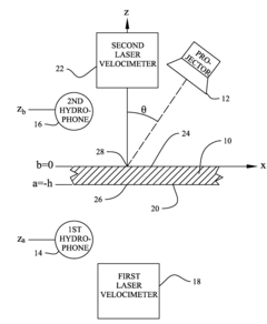
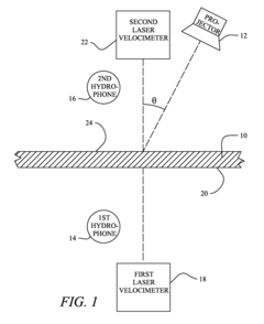
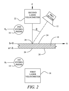
[0027]The coordinate system of the test configuration is shown in FIG. 2. Projector 12 is oriented at an angle θ with respect to sample 10. A first measurement location 28 is located on the far side of sample 10 from projector 12. This is the position where the beam from laser velocimeter 18 shown in FIG. 1 contacts surface 20. A second measurement location 26 corresponds to where second laser velocimeter 22 beam contacts surface 24. Under the coordinate system, the z axis is orthogonal to the second surface of sample 10 with the origin at this surface. Note that using this orientation results in b=0 and a having a value less than zero (−h). The thickness of the sample, h, is a positive value. The y axis is oriented into the page.
[0028]The system model has three governing differential equations that are coupled at their interfaces using conservation of linear momentum. The acoustic pressure in the fluid on the projector side of the test specimen is governed by the wave equation and ...
PUM
| Property | Measurement | Unit |
|---|---|---|
| thickness | aaaaa | aaaaa |
| frequency | aaaaa | aaaaa |
| thickness | aaaaa | aaaaa |
Abstract
Description
Claims
Application Information