Method and apparatus to provide compensation for parasitic inductance of multiple capacitors

a capacitor and parasitic inductance technology, applied in the direction of line-transmission, line-transmission details, current interference reduction, etc., can solve the problems of large real estate requirements, inability to provide coupled windings for each capacitor in a circuit, and limited size and performance of these filters

Inactive Publication Date: 2009-09-15
MASSACHUSETTS INST OF TECH
View PDF22 Cites 60 Cited by
  • Summary
  • Abstract
  • Description
  • Claims
  • Application Information

AI Technical Summary

Benefits of technology

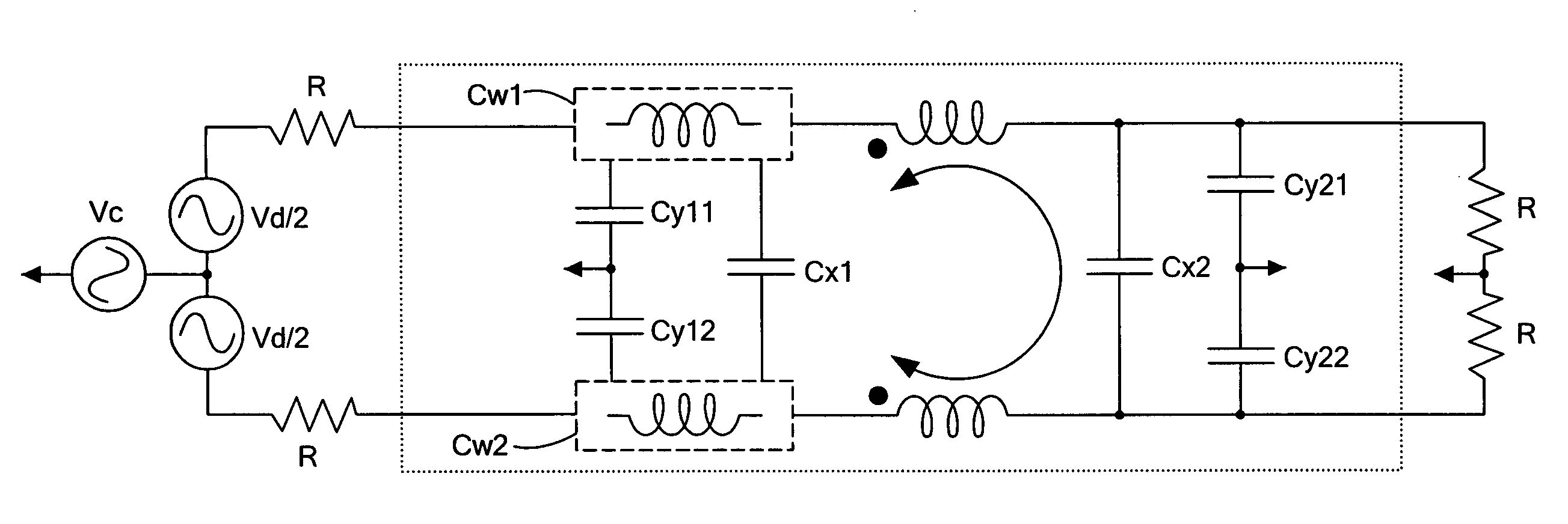
[0011]In a further aspect of the invention, a filter comprises a circuit including a first set of discrete magnetically-coupled windings having at least first and second capacitor tap points, a first capacitor having a first end connected to the first capacitor tap point, and a second capacitor having a first end connected to the second capacitor tap point. Induction of the first set of magnetically-coupled windings provides cancellation of an effect of an equivalent series inductance of a first path through the first capacitor and an equivalent series inductance of a second path though the second capacitor path, wherein an effect of capacitances of the first and second capacitors is not cancelled.

Problems solved by technology

The size and performance of these filters are often limited by filter capacitor parasitics, such as the equivalent series inductance (ESL) associated with magnetic energy storage in the capacitor and interconnects.
These parasitics cause non-ideal filter behavior at high-frequencies as the capacitor impedance is no longer dominated by its capacitance.
While the inductive component of a single capacitor can be cancelled as described above, providing coupled windings for each capacitor in a circuit can require significant real estate.

Method used


Image

  • Method and apparatus to provide compensation for parasitic inductance of multiple capacitors
  • Method and apparatus to provide compensation for parasitic inductance of multiple capacitors
  • Method and apparatus to provide compensation for parasitic inductance of multiple capacitors

Examples


example

[0064]A commercially available filter was used as a starting point as shown in FIG. 15A, which shows a filter schematic, and FIG. 15B, which shows a pictorial representation of the filter. As can be seen in FIG. 15B, the relatively large (15 μH) series inductors L11 and L12 are particularly bulky, heavy, and expensive components of the commercial filter. Thus, it would be desirable to eliminate them while preserving filter performance. In the illustrated filter, exemplary component values are set forth below in Table 1:

[0065]

TABLE 1Impedance ValuesComponentValueL11, L12 15 μHCY11, CY12 47 nF film capacitorCX1, CX22.2 μF film capacitorCY21, CY22 15 nF ceramic capacitor

[0066]As shown in FIGS. 16A (schematic) and 16B (pictorial representation), the series inductors (L11, L12 of FIG. 15B) were thus removed to provide working space for installing inductance cancellation windings CW1, CW2. Removal of the series inductors is offset through use of the significantly smaller cancellation wind...


PUM


Abstract

A coupled winding cancels parasitic inductance of first and second capacitors. In an EMI filter having common mode capacitors and a differential capacitors, first and second windings cancel parasitic inductance of the common mode and differential capacitors.

Description

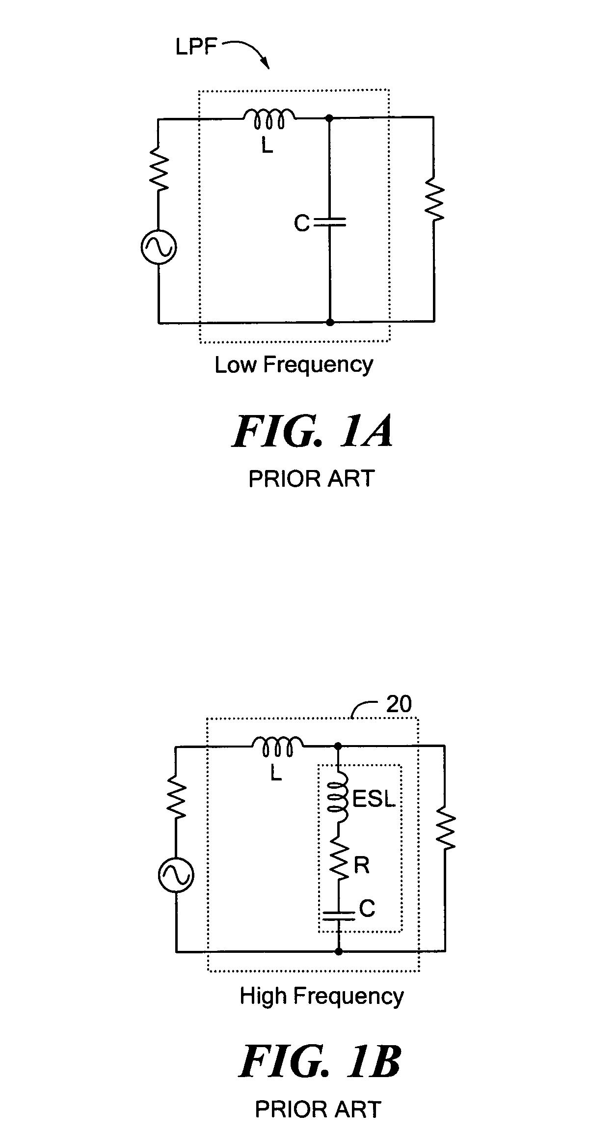
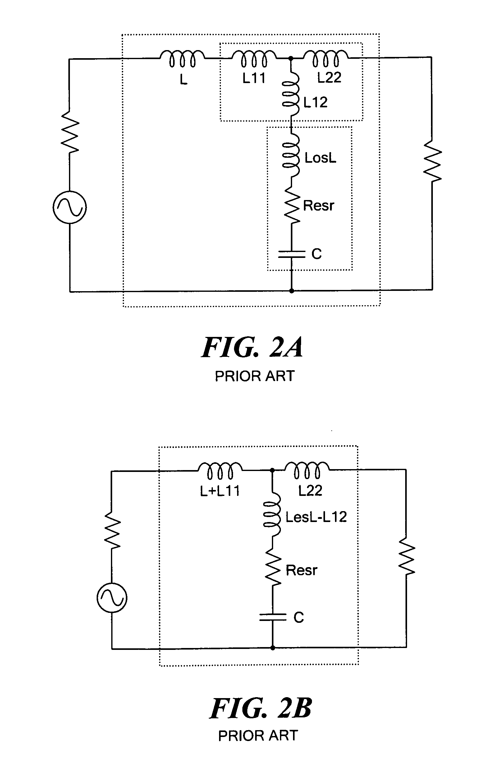
CROSS REFERENCE TO RELATED APPLICATIONS[0001]Not Applicable.STATEMENT REGARDING FEDERALLY SPONSORED RESEARCH[0002]Not Applicable.BACKGROUND OF THE INVENTION[0003]As is known in the art, electromagnetic interference (EMI) filters are used in many types of electrical equipment. Such filters play a role in meeting federal regulations for device compatibility, for example. The size and performance of these filters are often limited by filter capacitor parasitics, such as the equivalent series inductance (ESL) associated with magnetic energy storage in the capacitor and interconnects. Coupled magnetic windings can be used to compensate for the effects of parasitic inductance of capacitors, reducing the filter volume and increasing its attenuation performance.[0004]FIG. 1A shows a prior art LC low pass filter LPF having a capacitor C and an inductor L. FIG. 1B shows the filter of FIG. 1a with a high-frequency model 20 of the capacitor C. The high frequency capacitor model 20 includes the ...

Claims


Application Information

Patent Timeline
Patent Type & Authority Patents(United States)
IPC IPC(8): H03H7/00H04B3/28
CPCH03H7/427H03H2001/0014H03H2001/0057H03H2001/0035
Inventor PERREAULT, DAVID J.PIERQUET, BRANDON J.
Owner MASSACHUSETTS INST OF TECH
Why Eureka
Try Eureka