Reflector in liquid crystal display device and method of fabricating the same

a liquid crystal display device and reflector technology, applied in non-linear optics, instruments, optics, etc., can solve the problems of critical defeat, non-uniform brightness of displayed images, user difficulty in seeing images displayed in a display unit, etc., and achieve the effect of preventing light interferen

Active Publication Date: 2009-09-22
NEC LCD TECH CORP
View PDF18 Cites 5 Cited by
  • Summary
  • Abstract
  • Description
  • Claims
  • Application Information

AI Technical Summary

Benefits of technology

[0029]In view of the above-mentioned problems in the prior art, it is an object of the present invention to provide a reflector to be used in a liquid crystal display device, which is capable of preventing light interference caused by periodicity of wavy pattern to thereby avoid a reflector from being colored.
[0052]The first and second raised and recesses portions are different from each other with respect to a pitch between adjacent raised (or recessed) portions and a profile of an inclination angle of the raised and recessed portions. Thus, it is possible to delete the periodicity of wavy pattern. Accordingly, it is possible to avoid light interference caused by the periodicity of wavy pattern, and prevent a reflector from being colored.
[0053]Since the reflector is prevented from being colored due to light interference, it is no longer necessary to use light-diffusion adhesive in a light reflector. As a result, it is possible to reduce fabrication costs, and further, enhance a light-reflection rate and contrast. In particular, it is possible to enhance light-transmission contrast in a half-transmission type liquid crystal display device.

Problems solved by technology

This is because a light-transmission type liquid crystal display device used in a display unit of a note-type personal computer is accompanied with a problem that a user has difficulty in seeing images displayed in a display unit due to light reflection occurring at a surface of a display screen outdoors where sunlight is fierce.
In a mobile device often used outdoors, such phenomenon is a critical defeat.
However, if the wavy pattern is formed in random, light-reflection rates in pixels would not be uniform, resulting in non-uniformity in brightness in displayed images.
Accordingly, if a wavy pattern is formed in random in order to avoid light interference, the data volume would be vast, resulting in much difficulty in fabrication of a photomask.
Hence, it is difficult to remarkably change a profile of the inclination angle.
However, since the above-mentioned conventional methods of reducing light interference in a reflector include a step of forming wavy pattern at a surface of an organic film, it was not possible to delete the periodicity of an inclination angle of wavy pattern, and avoid a display screen from being colored due to light interference.
However, the light-diffusion adhesive causes reduction in a light reflection rate and reflection contrast due to light diffusion caused by the light-diffusive adhesive.
In particular, in a half-transmission type liquid crystal display device, since it is not possible to coat light-diffusive adhesion only onto an area in which the liquid crystal display device acts as a light-reflection type liquid crystal display device, there is caused a problem that the light-transmission contrast is lowered to about a half.
However, unlike an ordinary metal film, it is quite difficult to pattern the light-reflective particles.
In addition, particles often cause contaminants in a fabrication process, resulting in reduction in a fabrication yield.
Accordingly, it is not always possible to select a desired temperature for heating the light-reflective film.
Thus, the above-mentioned conventional methods cannot provide conditions necessary for formation of the small wavy pattern.
In addition, since common conditions are applied to a substrate in the above-mentioned conventional methods, it would not be possible to form small wavy pattern only in a part of a light-reflector.

Method used


Image

  • Reflector in liquid crystal display device and method of fabricating the same
  • Reflector in liquid crystal display device and method of fabricating the same
  • Reflector in liquid crystal display device and method of fabricating the same

Examples


first embodiment

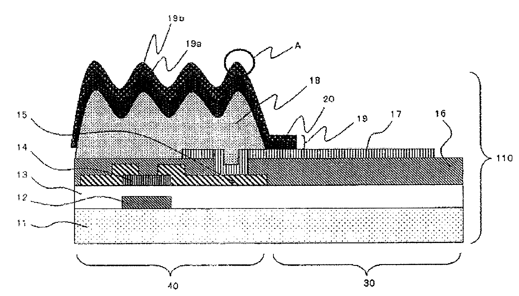
[0074]FIG. 3 is a cross-sectional view of a liquid crystal display device 100 including a reflector in accordance with the first embodiment of the present invention. Each of FIGS. 4 to 10 illustrates a step of a method of fabricating an active matrix substrate including the reflector in accordance with the first embodiment of the present invention. FIG. 11 is an enlarged cross-sectional view of the section A indicated in FIG. 9, and FIG. 12 is an enlarged cross-sectional view of the section A indicated in FIG. 10.

[0075]The liquid crystal display device 100 in accordance with the first embodiment is a half-transmission type liquid crystal display device including a light-transmission area 30 in which the liquid crystal display device 100 acts as a light-transmission type liquid crystal display device, and a light-reflection area 40 in which the liquid crystal display device 100 acts as a light-reflection type liquid crystal display device.

[0076]The liquid crystal display device 100 i...

second embodiment

[0129]FIG. 13 is a cross-sectional view of a liquid crystal display device 200 including a reflector in accordance with the second embodiment of the present invention.

[0130]The liquid crystal display device 200 is a light-reflection type liquid crystal display device including a light-reflector at which an external light is reflected, and display images by allowing the reflected light to pass therethrough or disallowing the reflected light to pass therethrough.

[0131]The liquid crystal display device 200 is comprised of an active matrix substrate 210, an opposing substrate 220 disposed in facing relation to the active matrix substrate 210, and a liquid crystal layer 130 sandwiched between the active matrix substrate 210 and the opposing substrate 220.

[0132]The active matrix substrate 210 is comprised of a first transparent substrate 11 composed of glass, a gate electrode 12 formed on the first transparent substrate 11 at the same side of the liquid crystal layer 130, a gate insulatin...

third embodiment

[0149]The liquid crystal display device 100 or 200 in accordance with the first or second embodiment may be applied to various electronic devices. As an example, the liquid crystal display device 100 is applied to a mobile phone in the third embodiment explained hereinbelow.

[0150]FIG. 17 is a block diagram of a mobile phone 275 including the liquid crystal display device 100.

[0151]The mobile phone 275 is comprised of a display unit 276, a controller 277 controlling an operation of the parts constituting the mobile phone 275, a memory 278 storing a program to be executed by the controller 277, and various data, a signal-receiver 279 through which radio signals are received, a signal-transmitter 281 through which radio signals are transmitted from the mobile phone 275, an input interface 282 comprised of a keyboard or a pointer, and a power source 283 providing power to the parts constituting the mobile phone 275.

[0152]The display unit 276 is comprised of a liquid crystal panel 265, a...


PUM

PropertyMeasurementUnit
thicknessaaaaaaaaaa
temperatureaaaaaaaaaa
wavelengthaaaaaaaaaa

Abstract

A reflector to be used in a liquid crystal display for reflecting an external light to display images therewith, including an organic film, and a reflective film formed covering the organic film therewith. The organic film has first raised and recessed portions at a surface thereof, and second raised and recessed portions formed at a surface of the first raised and recessed portions. The first raised and recessed portions include raised portions and recessed portions at least one of which is arcuate in cross-section, and the second raised and recessed portions are smaller in size than the first raised and recessed portions. The reflective film is shaped reflecting the first and second raised and recessed portions.

Description

BACKGROUND OF THE INVENTION[0001]1. Field of the Invention[0002]The invention relates to a reflector used in a liquid crystal display device, a method of fabricating the same, and a liquid crystal display device including the same.[0003]2. Description of the Related Art[0004]A liquid crystal display device is grouped into a light-transmission type liquid crystal display device, a light-reflection type liquid crystal display device, and a half-transmission type liquid crystal display device in accordance with a light-source thereof.[0005]A light-transmission type liquid crystal display device is designed to have a light-source at the rear of the device, and display images by allowing a light (called “backlight”) emitted from the light-source to pass therethrough or disallowing a light to pass therethrough.[0006]A light-reflection type liquid crystal display device is designed to have a light-reflector at which an external light is reflected, and display images by allowing the reflect...

Claims


Application Information

Patent Timeline
Patent Type & Authority Patents(United States)
IPC IPC(8): G02F1/1335
CPCG02F1/133553G02F1/136227G02F1/1335
Inventor KUDOU, YASUKISAKAMOTO, MICHIAKINAKA, KENICHIROU
Owner NEC LCD TECH CORP
Why Eureka
Try Eureka