
Electrical connector for use with printed circuit boards

a technology of printed circuit boards and electrical connectors, applied in the direction of coupling device connections, sustainable manufacturing/processing, final product manufacturing, etc., can solve the problem of presenting an oftentimes labor-intensive task

Active Publication Date: 2016-03-22
IDEAL IND INC
View PDF26 Cites 4 Cited by
  • Summary
  • Abstract
  • Description
  • Claims
  • Application Information

AI Technical Summary

Benefits of technology

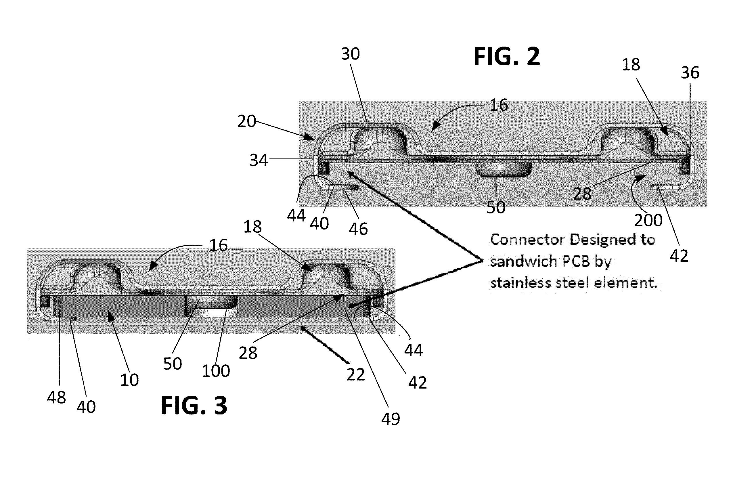
[0009]In a further described example, the body portion is provided with a single body portion having an electrical terminal. The single body portion is linked to a holding element that is cooperable with a corresponding element formed in one or more PCBs. A fastening element is also provided. The fastening element and the holding element (operating in cooperation with the corresponding element formed in the one or more PCBs) function to mechanically and electrically couple the body to the one or more PCBS. The holding element and corresponding element formed in the one or more PCBs also function inhibit movement of the body portion is at least two planar directions. The body can be arranged as above to prevent light interference with any LEDs carried by the PCBs, to be used as a jumper or a wire connector, etc.

Problems solved by technology

In either instance, to remove the PCB from the support structure underlying the connector, the connector must be removed from the PCB and from the support structure in order to provide access the PCB, thus presenting an oftentimes labor-intensive task.

Method used


Image

  • Electrical connector for use with printed circuit boards
  • Electrical connector for use with printed circuit boards
  • Electrical connector for use with printed circuit boards

Examples


Embodiment Construction

[0027]The following description of exemplary connectors and methods for using the same are not intended to limit the scope of the description to the precise form or forms detailed herein. Instead the following description is merely intended to be illustrative so that others may follow its teachings.

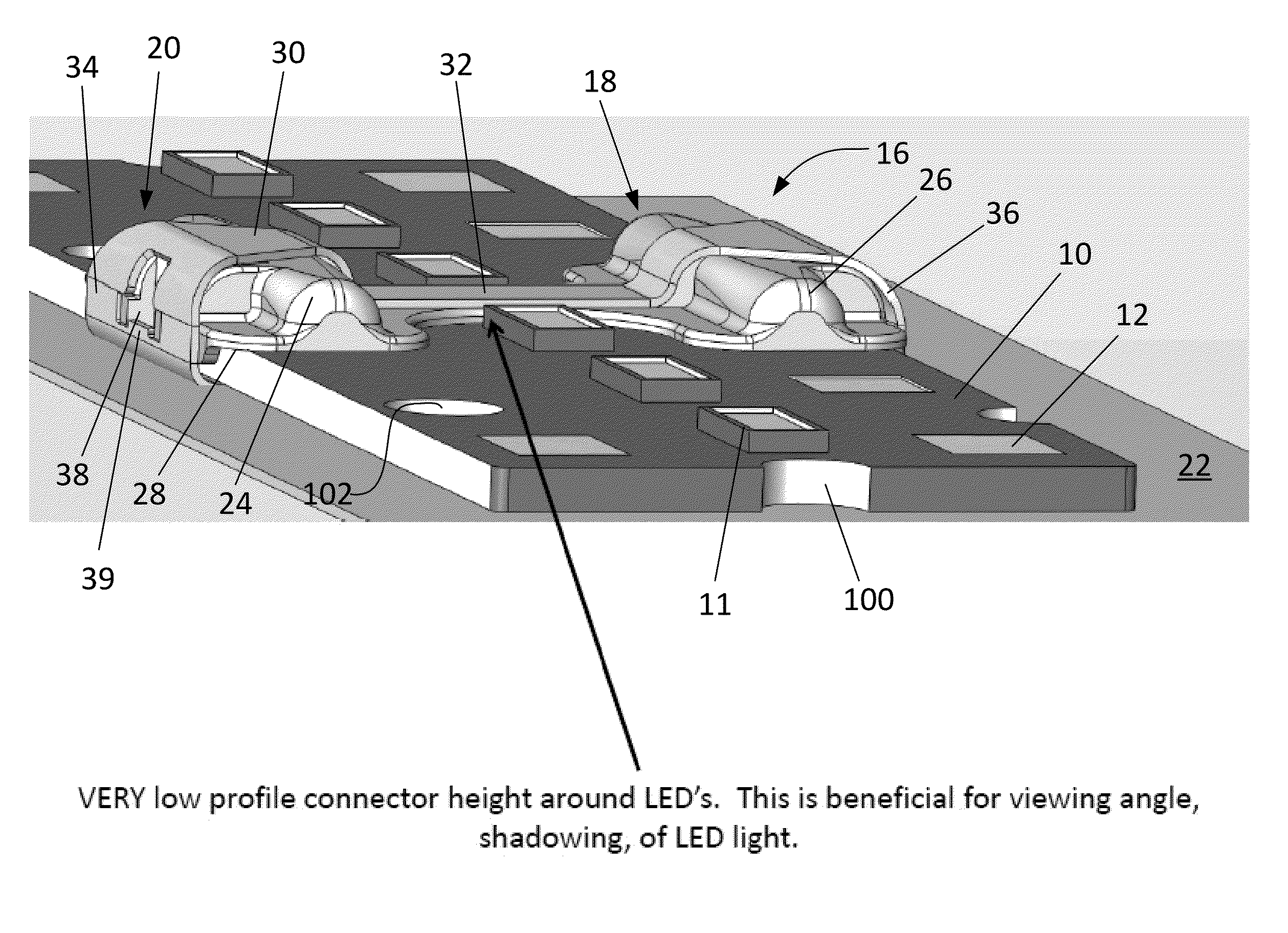
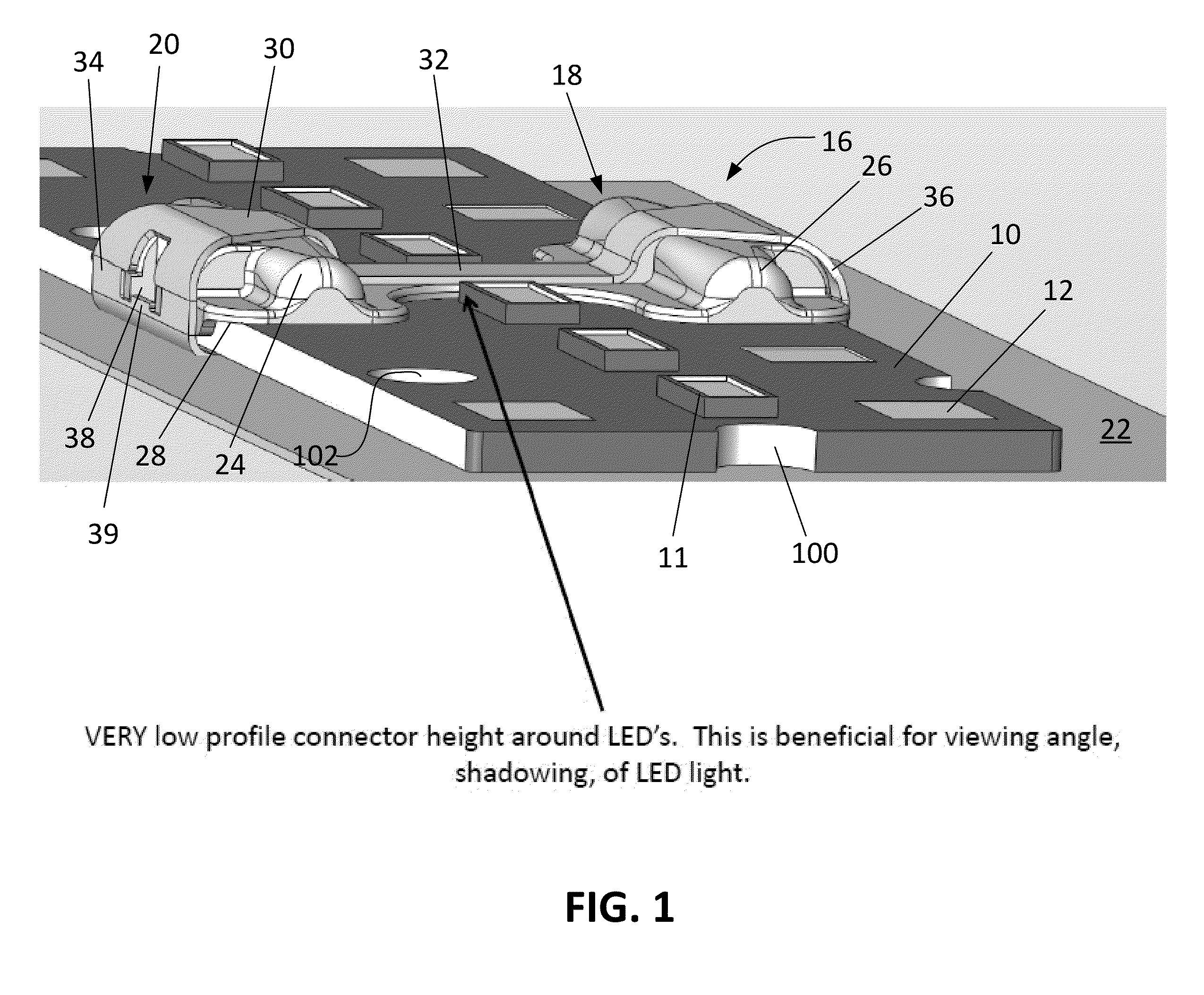
[0028]Turning now to the figures, wherein like elements are referenced using common identifiers, illustrated are exemplary connectors for use in connection with one or more printed circuit boards (“PCBs”). By way of non-limiting example, the PCBs 10, examples of which are illustrated in FIG. 1, may have mounted thereon one or more light emitting diodes (“LEDs”) 11 which are, in turn, electrically coupled to one or more contact pads 12 formed on a top side of the PCBs 10. The PCBs 10 are also provided with PCB apertures, slots, or the like 102 for use in receiving a fastener that is intended to be used to securely fasten the PCBs 10 to a mounting surface 22, such as a heat sink.

[0029]FIG. ...


PUM


Abstract

An electrical connector has one or more body portions in which is disposed an electrical terminal having at least one contact pad interface for coupling to a contact pad of at least one printed circuit board (PCB). The body has an associated fastening device which is used to mechanically and electrically couple the electrical connector to the at least one PCB. The electrical connector may be provided with a full or partial hourglass-like shape, when viewed from the side and / or from above, to facilitate its use with a PCB that carries a source of light, such as an LED.

Description

FIELD OF THE DISCLOSURE[0001]The following generally relates to electrical connectors and more particularly to electrical connectors for use with printed circuit boards.BACKGROUND OF RELATED ART[0002]Connectors, and, more particularly, connectors capable of electrically connecting printed circuit boards (“PCBs”) to one another are generally known in the art. For example, U.S. Pat. No. 7,892,022, entitled “Jumper Connector for a Lighting Assembly,” describes a connector for electrically connecting PCBs on which are mounted a plurality of light emitting diodes (“LEDs”). The described connector includes a connector body having a mating surface configured to engage more than one PCB. The connector body is configured to be secured to a substrate by a fastener. The connector body additionally includes a conductor and the conductor is configured to be electrically connected to the PCBs during the same step in which the connector body is secured to the substrate. In this manner, the connect...

Claims


Application Information

Patent Timeline
Patent Type & Authority Patents(United States)
IPC IPC(8): H01R12/00H01R4/48H01R11/01H01R12/73
CPCH01R12/732H01R4/4818H01R11/01H01R12/53H01R12/7023H01R12/714H05K2201/10424H05K1/142H05K3/368H05K2201/09163H05K2201/10189H05K2201/10265H05K2201/1031H01R12/7029H01R12/7052Y02P70/50H01R4/48185
Inventor ZANTOUT, ALAN, E.
Owner IDEAL IND INC
Learn More