Monolithic optical device for light transmission, and multi-channel optical system using same

a monolithic optical and light transmission technology, applied in semiconductor devices, lighting and heating devices, instruments, etc., can solve the problem of increasing the installation cost and other problems

Inactive Publication Date: 2002-12-05
HONEYWELL INT INC
View PDF2 Cites 4 Cited by
  • Summary
  • Abstract
  • Description
  • Claims
  • Application Information

AI Technical Summary

Benefits of technology

0003] A first object of the invention is to achieve a light-transmitting optical device in one single part able to eliminate any stray light rays not in the transmitting or receiving primary light beam passing through the objective. What is meant by primary light beam is all the light rays passing directly from one lens to the other. Any light ray taking a non-direct path is defined as being a stray ray.

Problems solved by technology

The large number of mechanical supports increases the cost price of the installation.

Method used


Image

  • Monolithic optical device for light transmission, and multi-channel optical system using same
  • Monolithic optical device for light transmission, and multi-channel optical system using same
  • Monolithic optical device for light transmission, and multi-channel optical system using same

Examples


Embodiment Construction

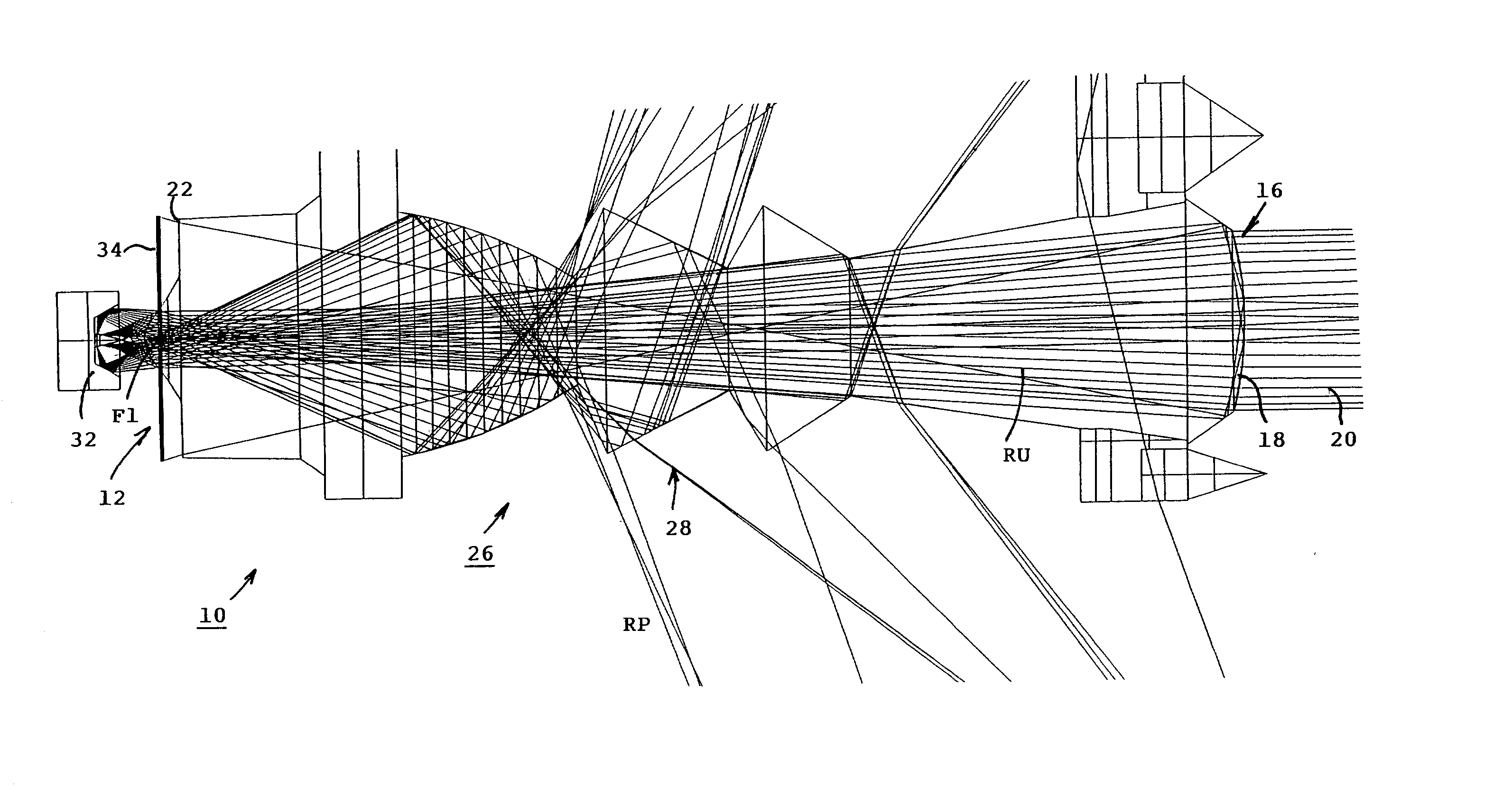
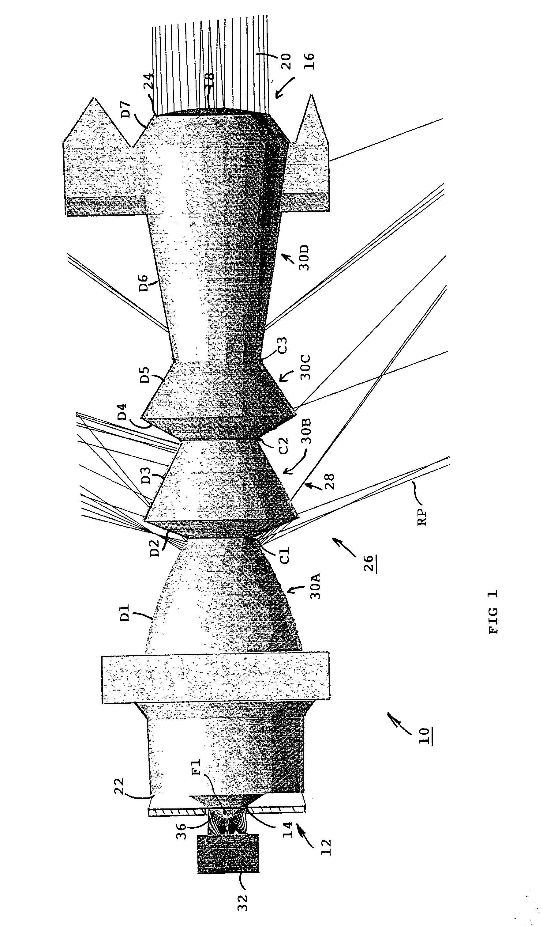
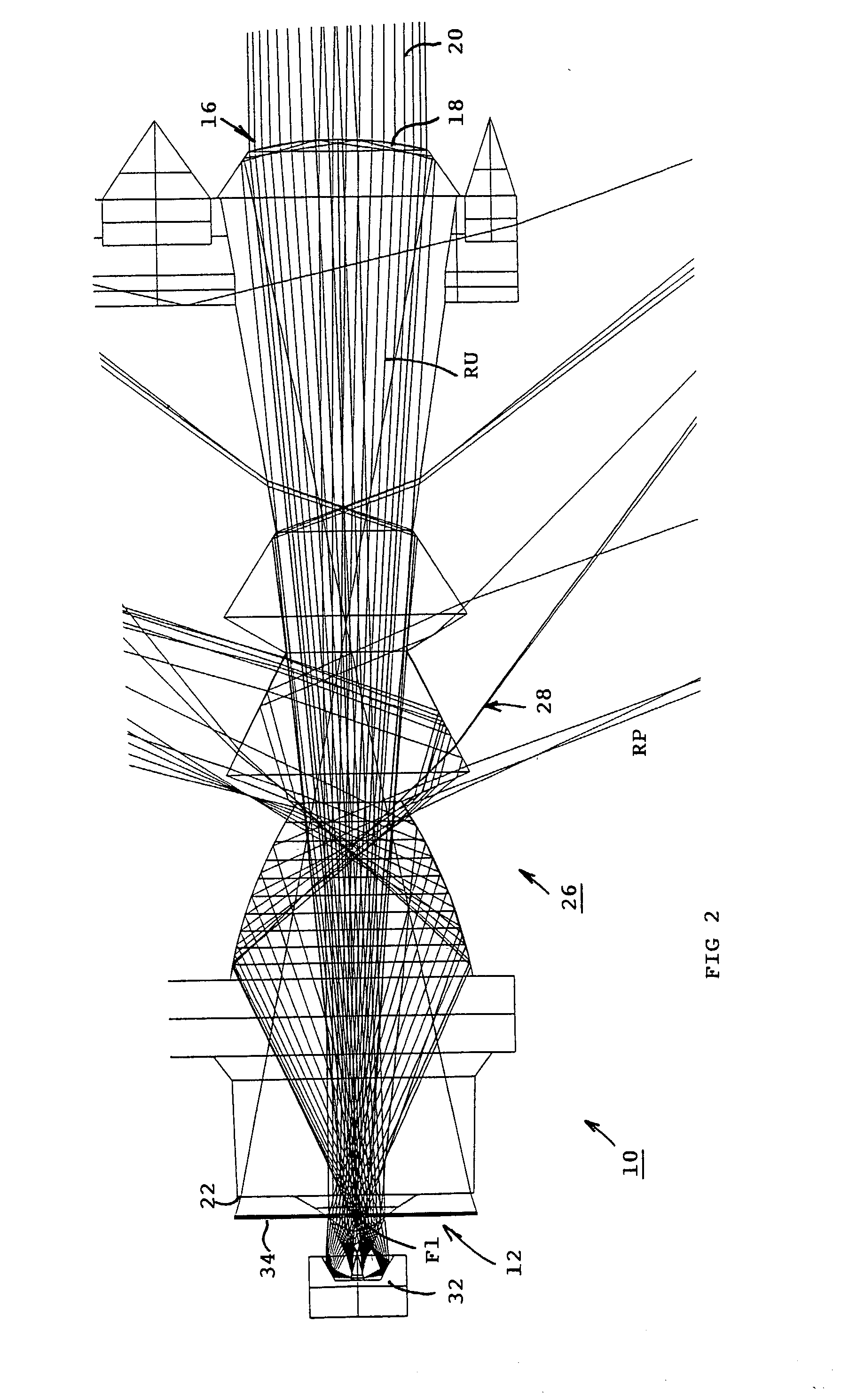
[0026] With reference to FIGS. 1 to 3, a light-transmitting optical device 10 comprises a condenser element 12 formed by a first lens 14 to concentrate the light in the opening of an objective 16 equipped with a second lens 18 designed to emit or receive an optical beam 20.

[0027] The first lens 14 of the condenser element 12 and the second lens 18 of the objective 16 are arranged respectively at one first end 22 and at a second opposite end 24 of an integrated optical module 26 achieved by a straight single-piece entity made of transparent material having a predetermined refractive index and a quality of transparency in the 360 nm to 1560 nm pass-band, i.e. in the visible and infrared field.

[0028] The intermediate zone 28 of the integrated optical module 26 comprises a plurality of deflectors 30A, 30B, 30C, 30D formed by a succession of dioptric surfaces D1 to D7 symmetrically arranged at intervals along the longitudinal direction of internal propagation of the light flux between th...


PUM


Abstract

An integrated light-transmission optical module for a safetyoptoelectronic barrier, comprises a condenser element having a first lens, and an objective having a second lens which are located respectively at a first end and a second end. The module comprises a single-piece entity made of transparent material, and having an intermediate zone provided with deflectors formed by a succession of dioptric surfaces distributed along the direction of light flux propagation between the first lens and the second lens. The deflectors ensure a deflection outside the optical module of stray rays reflected inside the module, so as to prevent transmission of strays rays, either through the second lens of the objective if it is a light transmission coming from the condenser element, or through the first lens when receiving light coming from the second lens.

Description

[0001] The invention relates to a light-transmitting optical device comprising a condenser element equipped with a first lens to concentrate the light in the opening of a second lens of an objective designed to emit or receive an optical beam.STATE OF THE ART[0002] Light-transmitting optical devices generally use a system of lenses and diaphragms arranged in an optical chamber. It is imperative to provide a mechanical support designed to position the different parts with respect to one another with precision. Opto-electronic barriers generally have two hundred monitoring light beams requiring a total of four hundred light-transmitting optical devices on the transmitter side and receiver side. The large number of mechanical supports increases the cost price of the installation.OBJECT OF THE INVENTION[0003] A first object of the invention is to achieve a light-transmitting optical device in one single part able to eliminate any stray light rays not in the transmitting or receiving pri...

Claims


Application Information

Patent Timeline
Patent Type & Authority Applications(United States)
IPC IPC(8): G02B17/00G02B17/08G02B27/00G02B27/30
CPCG02B17/002G02B27/0018G02B19/0061G02B19/0028G02B19/0076G02B19/0047F16P3/144F21K9/232
Inventor LENOIRE, DIDIERGODFROY, DOMINIQUEGIERCZAK, MAREK
Owner HONEYWELL INT INC
Why Eureka
Try Eureka