Supercharge Your Innovation With Domain-Expert AI Agents!

Friction plate for wet-type multiplate clutch

a multi-plate clutch and friction plate technology, applied in the direction of mechanical actuator clutches, friction linings, mechanical apparatus, etc., can solve the problems of insufficient drainage of lube oil on the friction surface, inability to satisfactorily meet the demand for a further reduction of drag torque, and inability to reduce drag torqu

Inactive Publication Date: 2009-10-06
NSK WARNER
View PDF11 Cites 2 Cited by
  • Summary
  • Abstract
  • Description
  • Claims
  • Application Information

AI Technical Summary

Benefits of technology

[0015]With the friction plate according to the present invention, the lube oil in the oil pocket produces cushioning effect in an initial stage of clutch engagement, thereby making it possible to avoid grabbing in the initial stage of clutch engagement.
[0016]The present invention has made it possible, with the above-described relatively simple construction, to avoid grabbing in an initial stage of clutch engagement while keeping a drag torque small during idling, even under such a lubrication environment that lots of lube oil are fed.

Problems solved by technology

With such conventional friction plates, no sufficient drainage of lube oil is feasible on their friction surfaces, thereby failing to satisfactorily meet the demand for a further reduction in drag torque.
Especially during rotation in a low-speed range, the drainage of intervening lube oil between the friction plates and the associated separator plates is not sufficient so that the drag torque cannot be reduced.
Especially when the clearances between the friction plates and the separator plates are small and the clutch is in a low rpm range, this tendency is pronounced so that a significant drag torque is produced due to the viscosity of the lube oil between the friction linings and their counterpart separator plates.
In an initial stage of clutch engagement, however, the lube oil which exists on each friction surface is quickly drained from the friction surface via these oil grooves and oil passages, and therefore, the cushioning effect of the lube oil is reduced to cause abrupt grabbing of the clutch in the initial stage of clutch engagement.
The use of this clutch as a clutch, a brake or the like in an automatic transmission causes a problem that a shock is produced when the automatic transmission is shifted.

Method used


Image

  • Friction plate for wet-type multiplate clutch
  • Friction plate for wet-type multiplate clutch
  • Friction plate for wet-type multiplate clutch

Examples


Embodiment Construction

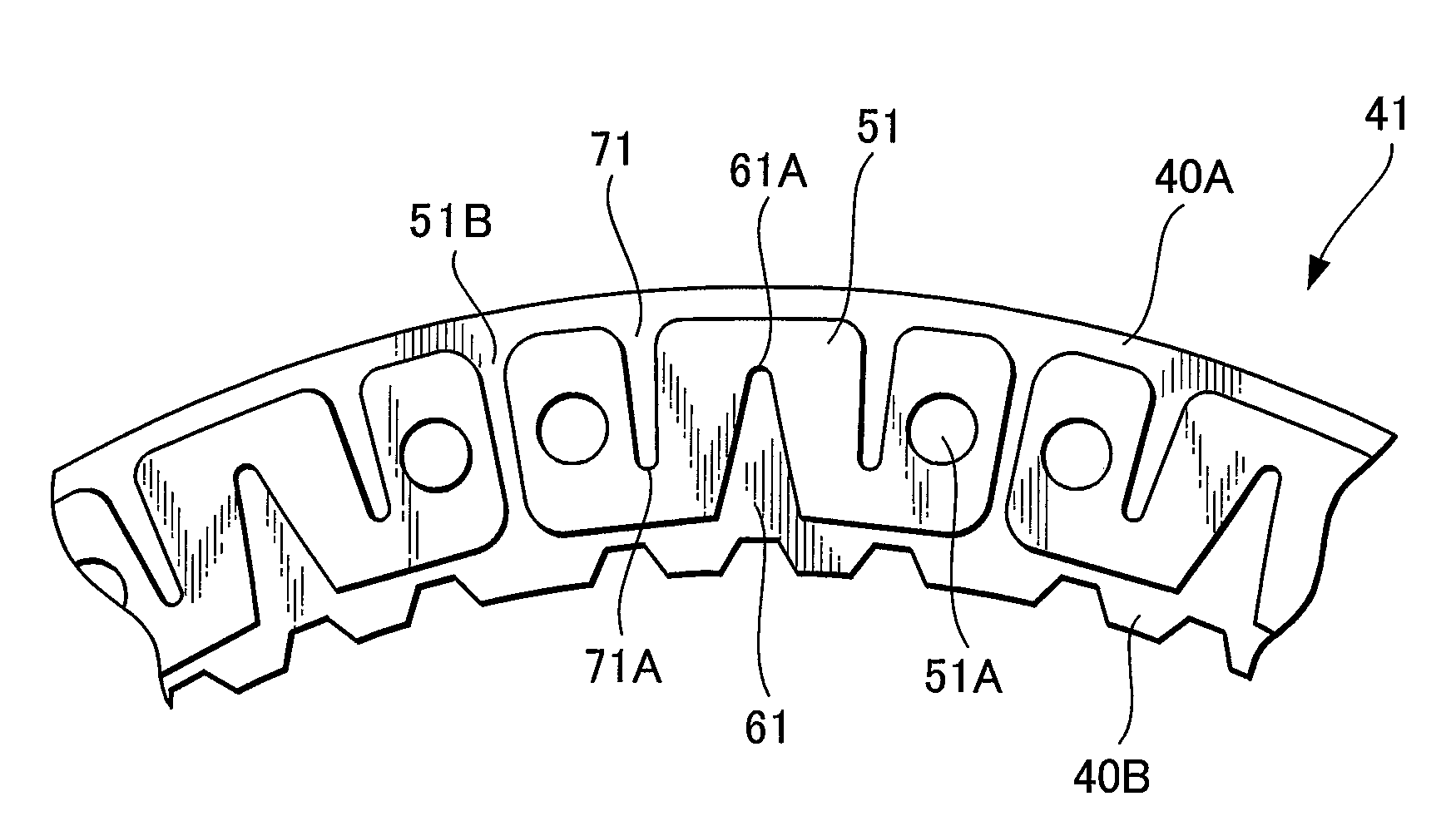
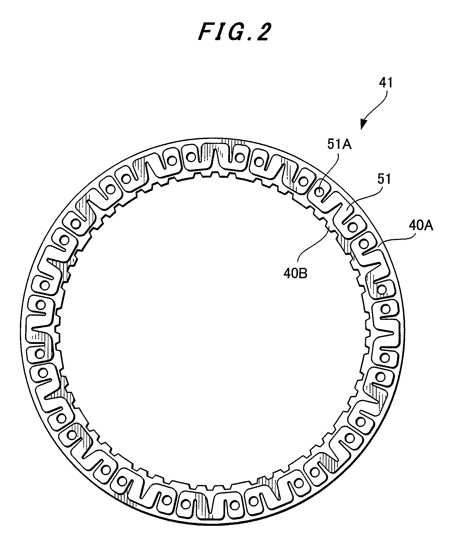
[0022]Each oil groove opening to the radially-outer side (i.e., the second oil groove) has oil-draining effect. Its oil drainage increases when its angular width is made greater from its closed end portion toward the radially-outer side.

[0023]Each oil groove opening to the radially-inner side (i.e., the first oil groove) is effective in separating the friction plate and its associated separator plate from each other, and this effect to separate the friction plate and the separator plate from each other becomes greater when its angular width is made narrower from its open end portion toward its closed end portion.

[0024]The shapes of the oil pocket and the first and second oil grooves can be appropriately determined depending upon the friction surface area, friction characteristics, lube-oil feed rate, and so on.

[0025]Certain preferred embodiments of the present invention will hereinafter be described with reference to the accompanying drawings. FIG. 2 is a front view of a friction pl...


PUM


Abstract

A friction plate for a wet-type multiplate clutch is provided with a core plate and friction linings bonded on opposite sides of the core plate, respectively. Each of the friction linings is composed of plural segment pieces bonded at angular intervals on the corresponding one of said opposite sides. The segment pieces each have at least one first oil groove and at least one second oil groove. The first oil groove opens to a radially-inner side of its corresponding segment piece and has a closed end portion located in a radially-intermediate part of the corresponding segment piece, and the second oil groove opens to a radially-outer side of the corresponding segment piece and has a closed end portion located in another radially-intermediate part of the corresponding segment piece. The segment pieces are each provided in a friction surface thereof with at least one oil pocket closed at a circumference thereof.

Description

CROSS-REFERENCE TO RELATED APPLICATION[0001]This application claims the priority of Japanese Patent Application 2007-026220 filed Feb. 6, 2007, which is incorporated herein by reference.FIELD OF THE INVENTION[0002]This invention relates to a friction plate for a wet-type multiplate cutch useful as a clutch, a brake or the like in an automatic transmission.BACKGROUND OF THE INVENTION[0003]FIG. 1 is a cross-sectional view illustrating the fundamental construction of a wet-type multiplate clutch 10. FIG. 1 shows a clutch casing 21, a counterpart hub 22 to which a torque is transmitted, a spline groove 23 formed on the clutch casing 21, a spline groove 24 formed on the hub 22, a piston 25 for pressing separator plates 30 and friction plates 40 against a backing plate 26, a snap ring 27 supporting the backing plate 26, and a sealing ring 28 for the piston 25. The separator plates 30 are maintained in fitting engagement with the spline groove 23, while the friction plates 40 are maintaine...

Claims


Application Information

Patent Timeline
Patent Type & Authority Patents(United States)
IPC IPC(8): F16D13/74
CPCF16D13/64F16D13/648F16D69/00F16D69/0408F16D13/74F16D2065/1312F16D25/123
Inventor KOBAYASHI, MASAHIROHIRAYANAGI, TSUYOSHITOYA, RITSUOYAMADA, MASAHIROHINO, HIROKAZU
Owner NSK WARNER
Features
  • R&D
  • Intellectual Property
  • Life Sciences
  • Materials
  • Tech Scout
  • Unparalleled Data Quality
  • Higher Quality Content
  • 60% Fewer Hallucinations
Learn More