Supercharge Your Innovation With Domain-Expert AI Agents!

Friction Plate for Wet-Type Multiplate Clutch

a multi-plate clutch and friction plate technology, applied in the direction of mechanical actuator clutches, friction linings, mechanical apparatus, etc., can solve the problems of not being able unable to drain lube oil on the friction surface, and unable to meet the demand for a further reduction in drag torqu

Inactive Publication Date: 2008-07-31
NSK WARNER
View PDF8 Cites 9 Cited by
  • Summary
  • Abstract
  • Description
  • Claims
  • Application Information

AI Technical Summary

Benefits of technology

[0013]Owing to the above-described construction, the friction plate according to the present invention has made it possible to avoid grabbing in an initial stage of clutch engagement because, when lube oil is drained from the recessed portions of each two adjacent segment pieces into the oil passage between the adjacent segment pieces upon clutch engagement, flows of the lube oil drained from the respective segment pieces run into each other to produce cushioning effect.
[0014]Even under such a lubrication environment that the clearances between friction plates and separator plates in a wet-type multiplate clutch are set narrow and lots of lube oil are fed, the present invention can avoid grabbing in an initial stage of clutch engagement while keeping a drag torque small during idling.

Problems solved by technology

Reflecting the demand for improvements in the shift response in an attempt to make not only an improvement in fuel economy and but also improvements in engine performance, the clearances between friction plates and their associated separator plates have become smaller in recent years than before, tending to result in a greater drag torque due to intervening oil films during idling.
With such conventional friction plates, no sufficient drainage of lube oil is feasible on their friction surfaces, thereby failing to satisfactorily meet the demand for a further reduction in drag torque.
Especially during rotation in a low-speed range, the drainage of intervening lube oil between the friction plates and the associated separator plates is not sufficient so that the drag torque cannot be reduced.
In an initial stage of clutch engagement, however, the lube oil which exists on each friction surface is quickly drained from the friction surface via these oil grooves and oil passages, and therefore, the cushioning effect of the lube oil is reduced to cause abrupt grabbing of the clutch in the initial stage of clutch engagement.
The use of this clutch as a clutch, a brake or the like in an automatic transmission causes a problem that a shock is produced when the automatic transmission is shifted.

Method used


Image

  • Friction Plate for Wet-Type Multiplate Clutch
  • Friction Plate for Wet-Type Multiplate Clutch
  • Friction Plate for Wet-Type Multiplate Clutch

Examples


first embodiment

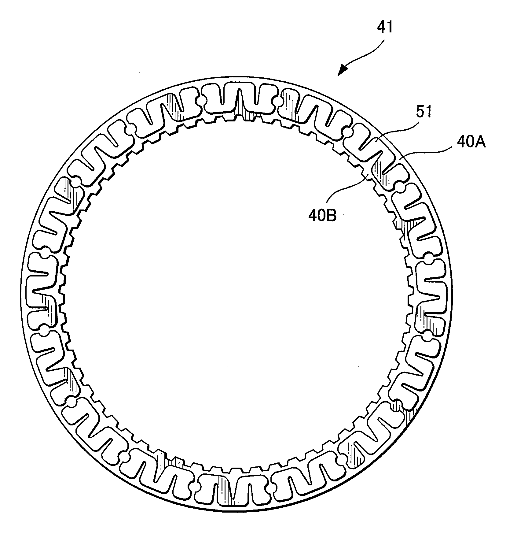
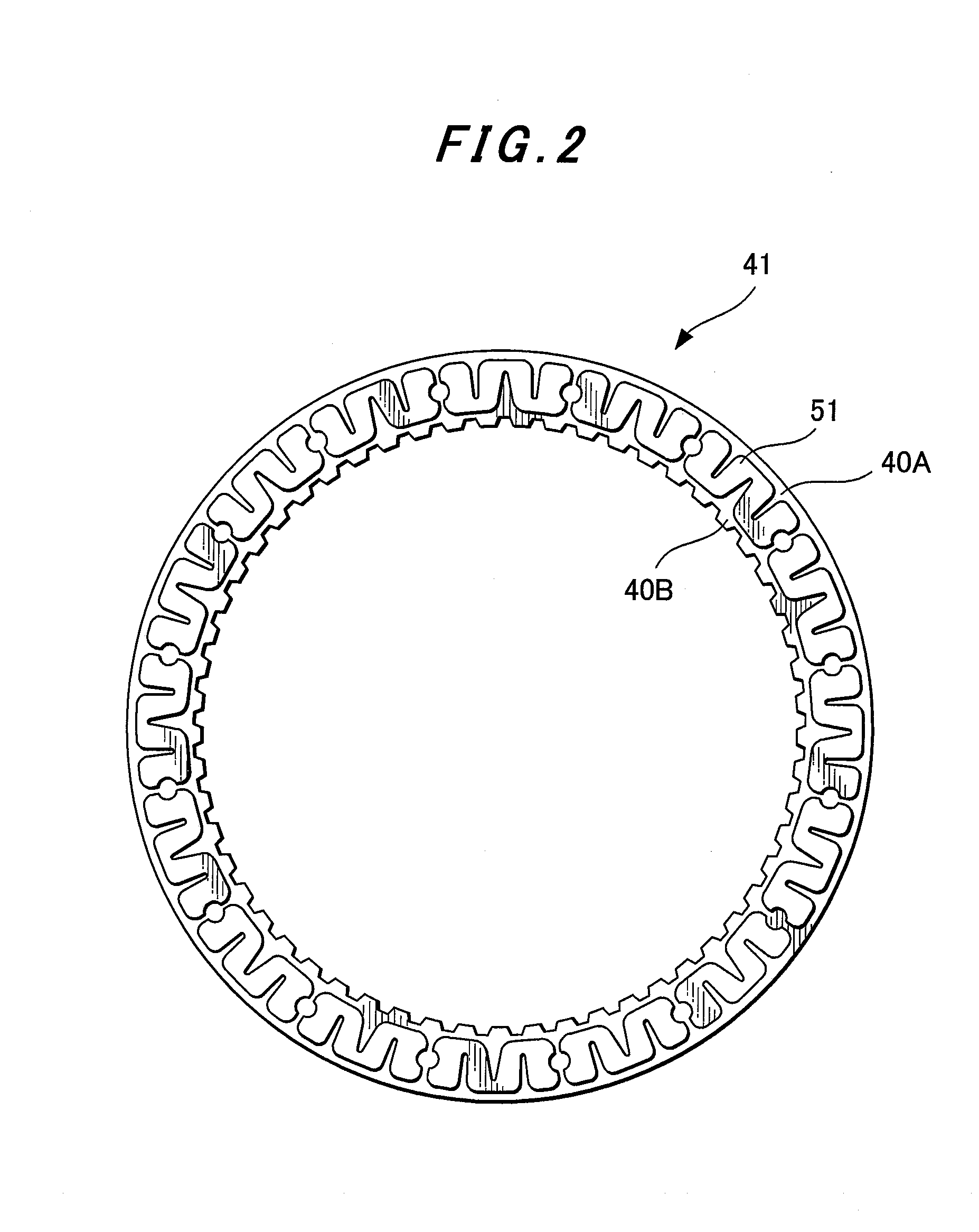
[0026]FIG. 2 is a front view of the friction plate 41 and FIG. 3 is an enlarged fragmentary front view of the friction plate 41 of FIG. 2. In this embodiment, recessed portions arranged in the opposing side walls 81A, 81B of each two adjacent segment pieces 51, 51 are formed as semi-circular recessed portions 91A, 91B. In each segment piece 51, a first oil groove 61 opening to a radially-inner side of the segment piece 51 (hereinafter called “the first oil groove”) and second oil grooves 71 opening to a radially-outer side of the segment piece 51 (hereinafter called “the second oil grooves”) are formed in V-shapes so that their angular widths become wider from their closed end portions 61B, 71A toward their open end portions, respectively. Further, the closed end portions 61B, 71A are located beyond a radial center line of the segment piece 51, respectively.

[0027]FIG. 4 depicts the friction plate 42 according to the second embodiment. Recessed portions arranged in the opposing side...

fifth embodiment

[0029]FIG. 7 depicts the friction plate 45 according to the Recessed portions 95A, 95B arranged in the opposing side walls 85A, 85B of each two adjacent segment pieces 55, 55 are constricted at openings 105A, 105B thereof in the side walls 85A, 85B.

[0030]It is to be noted that in FIG. 4 through FIG. 7, the shapes of the first grooves 62 to 65 and second grooves 72 to 75 and the positions of their closed end portions (not identified by reference numerals) are exactly the same as the shapes of the corresponding grooves 61, 71 and the positions of their closed end portions 61B, 71A in FIG. 3.

[0031]FIG. 8 diagrammatically illustrates advantageous effects of the present invention, in which transmitted torque is plotted along the ordinate while time is plotted along the abscissa. A broken line B shows time-torque characteristics of a conventional clutch, while a solid line A corresponds to the present invention. The conventional clutch developed grabbing in an initial stage of clutch eng...


PUM


Abstract

A friction plate for a wet-type multiplate clutch is provided with a core plate and friction linings bonded on opposite sides of the core plate, respectively. Each of the friction linings is composed of plural segment pieces bonded at angular intervals on the corresponding one of said opposite side. The segment pieces each have at least one first oil groove and at least one second oil groove. The first oil groove opens to a radially-inner side of its corresponding segment piece and has a closed end portion located in a radially-intermediate part of the corresponding segment piece. The second oil groove opens to a radially-outer side of the corresponding segment piece and has a closed end portion located in another radially-intermediate part of the corresponding segment piece. Each two adjacent ones of the segment pieces are provided, in radially-middle parts of opposing side walls thereof, with angularly-extending recessed portions, respectively.

Description

CROSS-REFERENCE TO RELATED APPLICATION[0001]This application claims the priority of Japanese Patent Application 2007-018629 filed Jan. 30, 2007, which is incorporated herein by reference.FIELD OF THE INVENTION[0002]This invention relates to a friction plate for a wet-type multiplate cutch useful as a clutch, a brake or the like in an automatic transmission.BACKGROUND OF THE INVENTION[0003]FIG. 1 is a cross-sectional view illustrating the fundamental construction of a wet-type multiplate clutch 10. FIG. 1 shows a clutch casing 21, a counterpart hub 22 to which rotations are to be transmitted, a spline groove 23 formed on the clutch casing 21, a spline groove 24 formed on the hub 22, a piston 25 for pressing separator plates 30 and friction plates 40 against a backing plate 26, a snap ring 27 supporting the backing plate 26, and a sealing ring 28 for the piston 25. The separator plates 30 are maintained in fitting engagement with the spline groove 23, while the friction plates 40 are ...

Claims


Application Information

Patent Timeline
Patent Type & Authority Applications(United States)
IPC IPC(8): F16D13/64
CPCF16D13/64F16D13/648F16D2065/1312F16D69/00F16D69/0408F16D13/74F16D25/123F16D25/0638F16D13/72
Inventor KOBAYASHI, MASAHIROKINPARA, HIROYUKI
Owner NSK WARNER
Features
  • R&D
  • Intellectual Property
  • Life Sciences
  • Materials
  • Tech Scout
  • Unparalleled Data Quality
  • Higher Quality Content
  • 60% Fewer Hallucinations
Learn More