Friction plate for wet-type multiplate clutch
a multi-plate clutch and friction plate technology, which is applied in the direction of mechanical actuated clutches, friction linings, mechanical apparatus, etc., can solve the problems of not being able unable to drain lube oil on their friction surfaces, and unable to meet the demand for a further reduction in drag torqu
- Summary
- Abstract
- Description
- Claims
- Application Information
AI Technical Summary
Benefits of technology
Problems solved by technology
Method used
Image
Examples
first embodiment
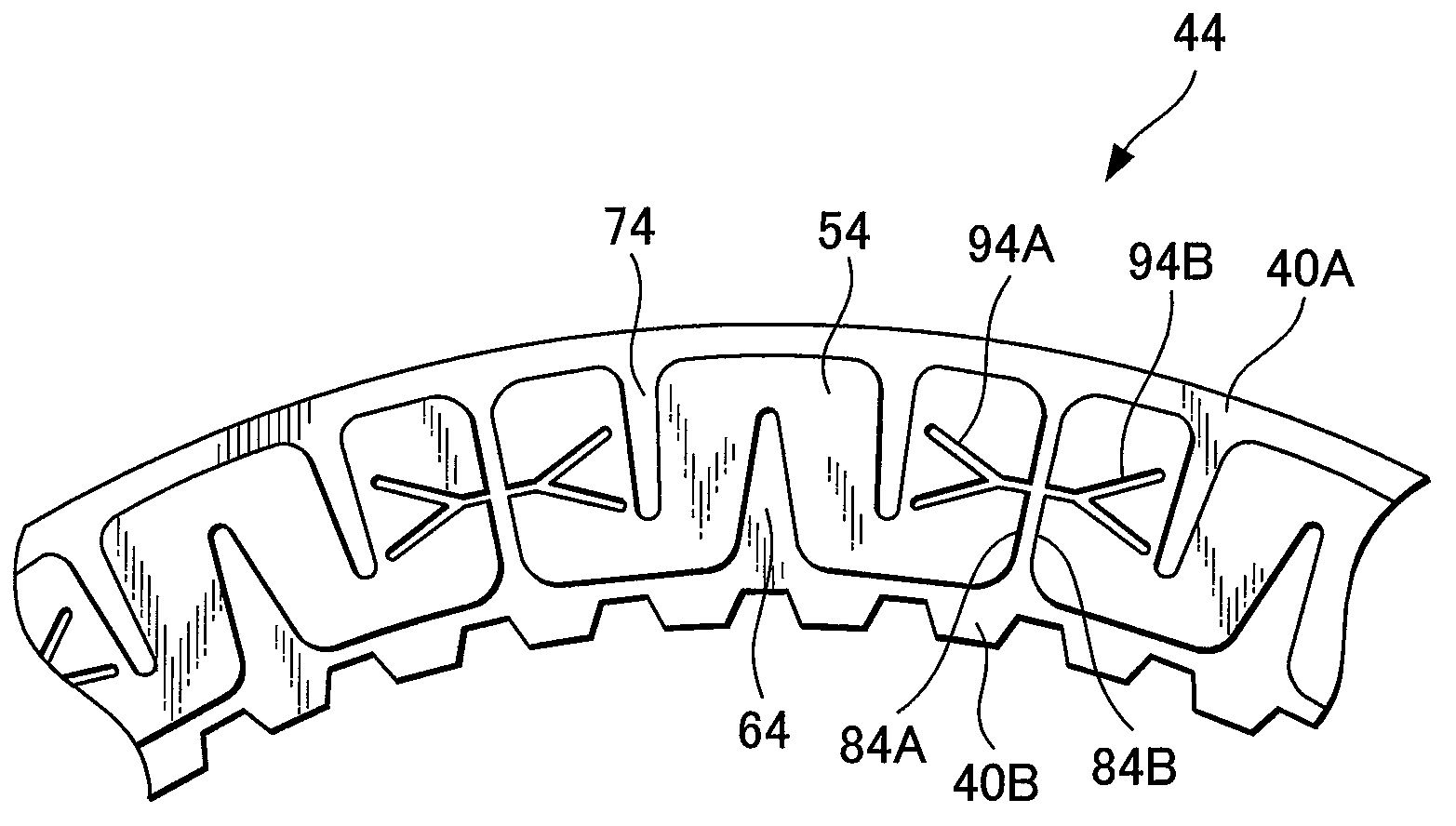
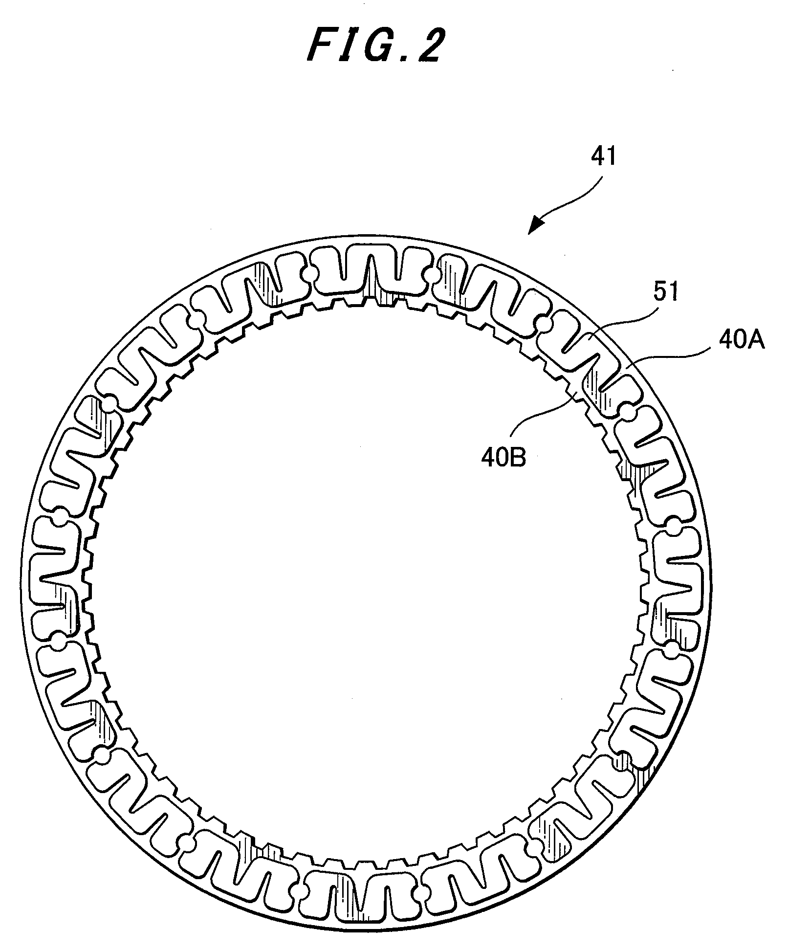
[0026]FIG. 2 is a front view of the friction plate 41 and FIG. 3 is an enlarged fragmentary front view of the friction plate 41 of FIG. 2. In this embodiment, recessed portions arranged in the opposing side walls 81A, 81B of each two adjacent segment pieces 51, 51 are formed as semi-circular recessed portions 91A, 91B. In each segment piece 51, a first oil groove 61 opening to a radially-inner side of the segment piece 51 (hereinafter called “the first oil groove”) and second oil grooves 71 opening to a radially-outer side of the segment piece 51 (hereinafter called “the second oil grooves”) are formed in V-shapes so that their angular widths become wider from their closed end portions 61B, 71A toward their open end portions, respectively. Further, the closed end portions 61B, 71A are located beyond a radial center line of the segment piece 51, respectively.
[0027]FIG. 4 depicts the friction plate 42 according to the second embodiment. Recessed portions arranged in the opposing side...
fifth embodiment
[0029]FIG. 7 depicts the friction plate 45 according to the Recessed portions 95A, 95B arranged in the opposing side walls 85A, 85B of each two adjacent segment pieces 55, 55 are constricted at openings 105A, 105B thereof in the side walls 85A, 85B.
[0030]It is to be noted that in FIG. 4 through FIG. 7, the shapes of the first grooves 62 to 65 and second grooves 72 to 75 and the positions of their closed end portions (not identified by reference numerals) are exactly the same as the shapes of the corresponding grooves 61, 71 and the positions of their closed end portions 61B, 71A in FIG. 3.
[0031]FIG. 8 diagrammatically illustrates advantageous effects of the present invention, in which transmitted torque is plotted along the ordinate while time is plotted along the abscissa. A broken line B shows time-torque characteristics of a conventional clutch, while a solid line A corresponds to the present invention. The conventional clutch developed grabbing in an initial stage of clutch eng...
PUM
 Abstract
Description
Claims
Application Information
 - R&D
- Intellectual Property
- Life Sciences
- Materials
- Tech Scout
- Unparalleled Data Quality
- Higher Quality Content
- 60% Fewer Hallucinations
Browse by: Latest US Patents, China's latest patents, Technical Efficacy Thesaurus, Application Domain, Technology Topic, Popular Technical Reports.
© 2025 PatSnap. All rights reserved.Legal|Privacy policy|Modern Slavery Act Transparency Statement|Sitemap|About US| Contact US: help@patsnap.com


