Optical disc apparatus, tracking control method, and integrated circuit

a technology of optical discs and control methods, applied in the field of optical disc apparatuses, can solve the problems of inability to detect wobble signals, inability to move light beams to the position, and inability to measure wobble signals

Inactive Publication Date: 2009-11-10
SOCIONEXT INC
View PDF12 Cites 3 Cited by
  • Summary
  • Abstract
  • Description
  • Claims
  • Application Information

AI Technical Summary

Benefits of technology

[0017]The present invention is made in view of the problems noted above and aims to provide an optical disc apparatus capable of improving the accuracy of tracking control, even if the focusing lens and possibly other elements are positionally deviated at the initial state before tracking control.
[0024]In addition, the optical disc apparatus according to the present invention is applicable to tracking control of DVD-RAM and other optical discs having the above noted characteristic and still achieves highly precise tracking control. The highly precise tracking control is achieved by accurately detecting the positional deviation between the beam spot and the center line of the track, resulting from the positional deviation of one or more detecting elements.
[0026]When the light receiving areas are located at different positions along the radial direction of the optical disc and the modulation factors of two signals indicative of light received on the respective light receiving areas are equal to each other, it means that the center of the light receiving areas of the photodetector corresponds to the center line of the track. As a result, the reflected light received on the respective light receiving areas located relatively outwardly and inwardly is equal to each other in terms of the ratio between the high- and low-frequency components contained therein. Thus, by determining, as the correction value, the driving value of the focusing lens used when the resulting modulation factors are equal or substantially equal to each other, the positional deviation of the detecting elements are corrected before tracking control so as to bring the center of the light receiving areas of the photodetector to a position corresponding to the center line of the track. With this arrangement, the tracking control is performed with improved accuracy.
[0028]With the above structure, the modulation factors are measured with different preset values. The preset values are used for sequentially moving the focusing lens along the radial direction of the optical disc to predetermined positions that are located at a predetermined space interval. This structure allows for easy setting of the preset value to be input next. In addition, an optimum driving value for moving the focusing lens along the radial direction of the optical disc is determined as the correction value. As a result, the accuracy of tracking control improves.
[0030]With the above structure, even if the optical disc has different characteristics at relatively inward and outward areas thereof, a correction value is determined for each of a plurality of radial positions on the optical disc, including for example, relatively inward and outward radial positions. Thus, the tracking control is more accurately performed as compared with tracking control performed based on a single correction value determined for a single radial position on the optical disc that is relatively away from the radial position of the desired track.

Problems solved by technology

Unfortunately, however, JP patent application publication No. 2000-20968 has the setback described below.
That is, the wobble signal cannot be detected unless the optical beam is on track.
In the case where the focusing lens and / or the photodetector are deviated at the initial state before tracking control, the tracking control cannot be initiated, so that the light beam cannot be moved to the position on the desired track of the optical disc.
Thus, the wobble signal measurement is impossible in such a case.
Thus, the technique disclosed in JP patent application publication No. 2000-20968 is not applicable for tracking control adjustment of DVD-ROM.
It is thus difficult to improve the accuracy of correction when the disclosed technique is applied to DVD-RAM and other optical discs having a characteristic similar to DVD-RAM.

Method used


Image

  • Optical disc apparatus, tracking control method, and integrated circuit
  • Optical disc apparatus, tracking control method, and integrated circuit
  • Optical disc apparatus, tracking control method, and integrated circuit

Examples


embodiment 1

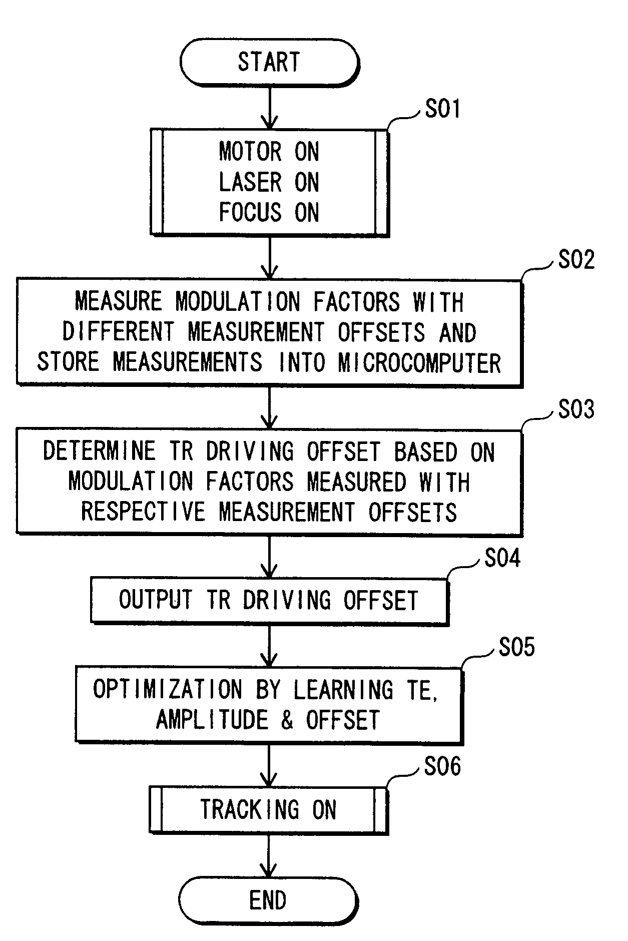
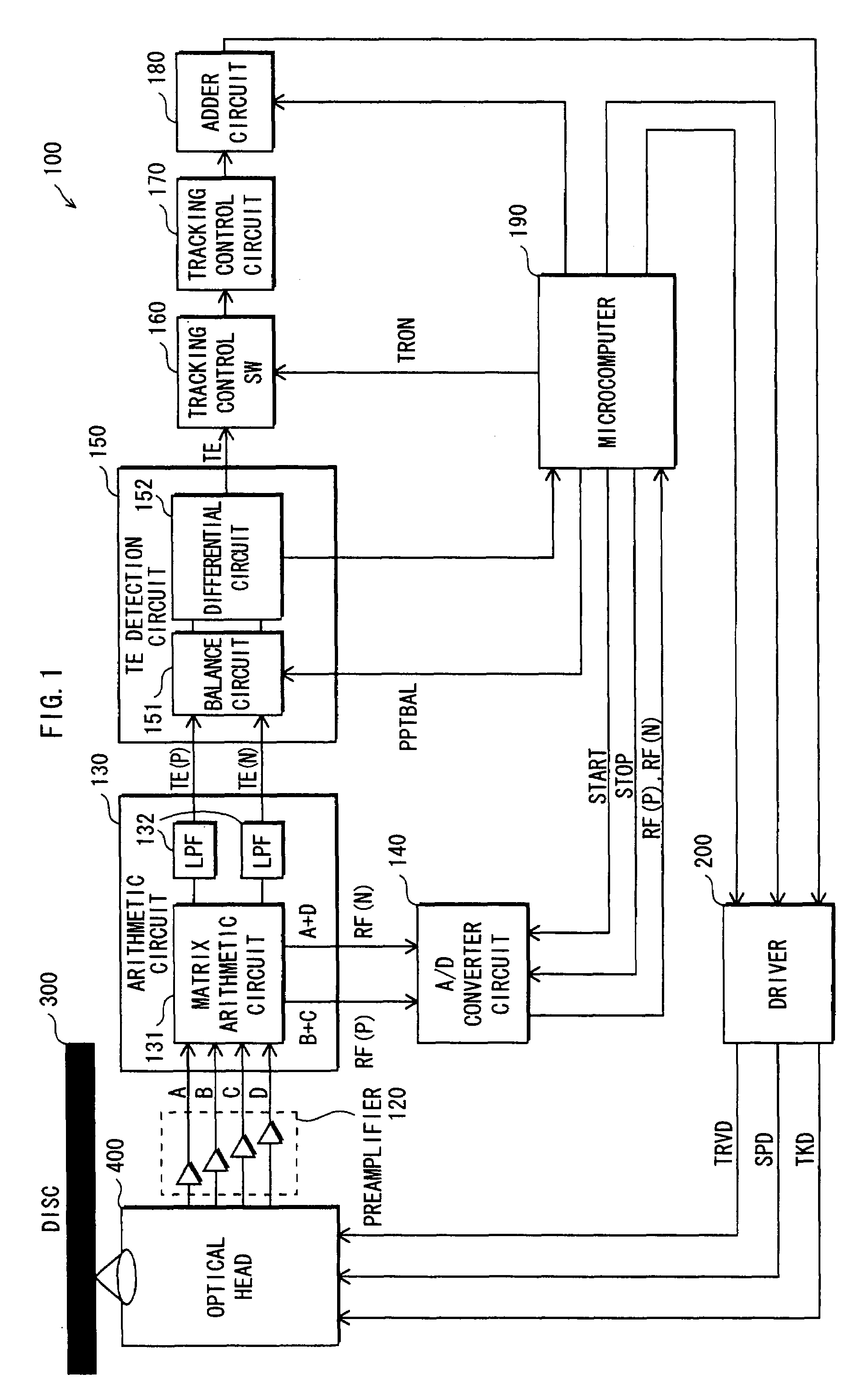
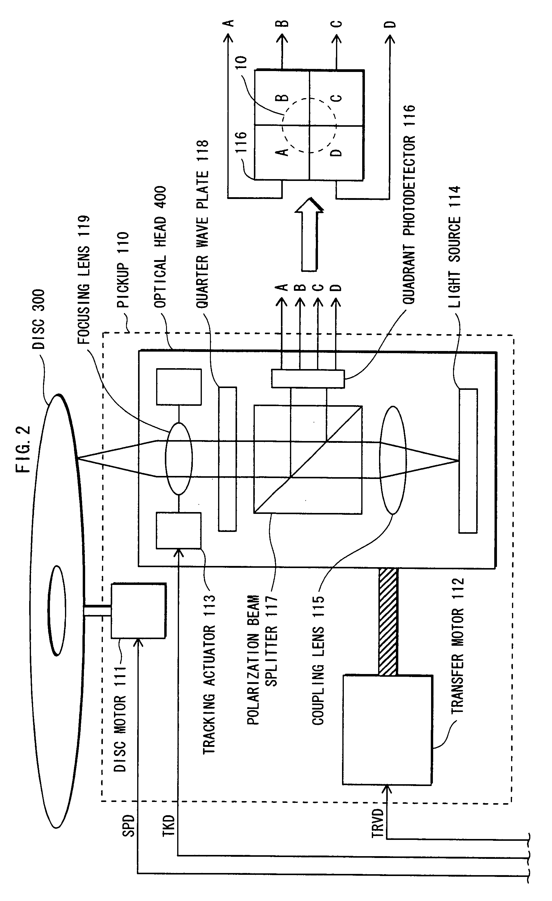
[0043]Suppose that a detecting element deviates from a position corresponding to the center line of a desired track of an optical disc at the initial state before tracking control. Due to the positional deviation of the detecting element, the beam spot on the optical disc deviates from the center line of the track. In such a case, an optical disc apparatus according to the present invention determines a correction value for correcting the positional deviation based on measurement signals and sets a focusing lens drive to move a focusing lens according the correction value. Then, the optical disc apparatus corrects a TE signal based on the symmetry of the TE signal amplitude in a conventional manner and drives a tracking control circuit based on the corrected TE signal. The tracking control is performed based on a sum signal of the correction value and a control value, which is an output value of the tracking control circuit.

[0044]In the present embodiment, a TE signal is detected ac...


PUM

PropertyMeasurementUnit
frequencyaaaaaaaaaa
timeaaaaaaaaaa
structureaaaaaaaaaa

Abstract

An optical disc apparatus has: an optical head 400 for emitting a light beam onto a predetermined track of an optical disc 300 before tracking control in order to detect reflected light with a photodetector; an arithmetic circuit 130 for generating measurement signals each indicative of a time-varying change of light received on a respective one of a plurality of light receiving areas of the photodetector; an A / D converter circuit 140 for A / D converting each measurement signal; a microcomputer 190 for determining a correction value based on a difference, in terms of high- and low-frequency components, between measurement signals having been A / D converted; and an adder circuit 180 for adding the correction value to a driving value output from a tracking control circuit 170, so that the driving value is corrected.

Description

BACKGROUND OF THE INVENTION[0001](1) Field of the Invention[0002]The present invention relates to an optical disc apparatus and more particularly to tracking control[0003](2) Description of the Related Art[0004]The following describes tracking control according to the state of the art, with reference to FIG. 7.[0005]FIG. 7 illustrate various states in which a quadrant photodetector 116 receives light reflected from an optical disc without tracking control. FIG. 7 also illustrate a tracking error signal 11 (hereinafter, “TE signal”) generated responsive to the reflected light received by the quadrant photodetector 116 in each state. The reference potential illustrated in each FIG. 7 is the reference potential of a non-illustrated circuit for tracking control (hereinafter, “tracking control circuit”).[0006]The tracking control circuit is designed to achieve tracking control in the manner described below. It is noted that the amplitude center of a TE signal corresponds to the center li...

Claims


Application Information

Patent Timeline
Patent Type & Authority Patents(United States)
IPC IPC(8): G11B7/095
CPCG11B7/131G11B7/0945G11B7/0938G11B7/0903G11B7/0906
Inventor MIYAZAKI, KAZUHIKOMASAKI, KIYOSHISHIRANE, HIDEKI
Owner SOCIONEXT INC
Why Eureka
Try Eureka